EasyManuals Logo

ABB ACS355 series Supplement

ABB ACS355 series
47 pages
To Next Page IconTo Next Page
To Previous Page IconTo Previous Page
Page #19 background imageLoading...
Page #19 background image
Mechanical installation
37
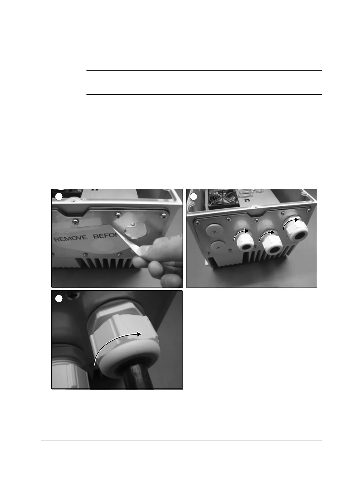
Installing the cable glands (optional, +H376)
Note: The lead-throughs are only meant for sealing the enclosure. Do not use them
for grounding.
1. Remove the sticker labeled REMOVE BEFORE USE.
2. Tighten the cable glands that you want to use with their back nuts. The tightening
torque depends on the cable gland size. See Tightening torques on page 38.
3. Lead the cable through the gland and tighten until the gasket of the lead-through
is tightly around the cable. The cable diameter depends on the cable gland size:
M12: 3.5…7.0 mm
M25: 9.0…17.0 mm
M32: 11.0…21.0 mm
1 2
3
Buy: www.ValinOnline.com | Phone 844-385-3099 | Email: CustomerService@valin.com

Table of Contents

Other manuals for ABB ACS355 series

Questions and Answers:

Question and Answer IconNeed help?

Do you have a question about the ABB ACS355 series and is the answer not in the manual?

ABB ACS355 series Specifications

General IconGeneral
Power Range0.37 to 22 kW
Protection ClassIP20
Output Frequency0 to 500 Hz
Braking ChopperBuilt-in
Control MethodScalar control, Vector control
Ambient Temperature-10 to +50 °C
Communication ProtocolsModbus, CANopen
Protection FeaturesOvercurrent, Overvoltage, Undervoltage, Overtemperature
Cooling MethodAir-cooled
Number of Phases3-phase

Related product manuals