controlling AC motors. The construction of frame sizes R1 and R3 varies to some
extent.
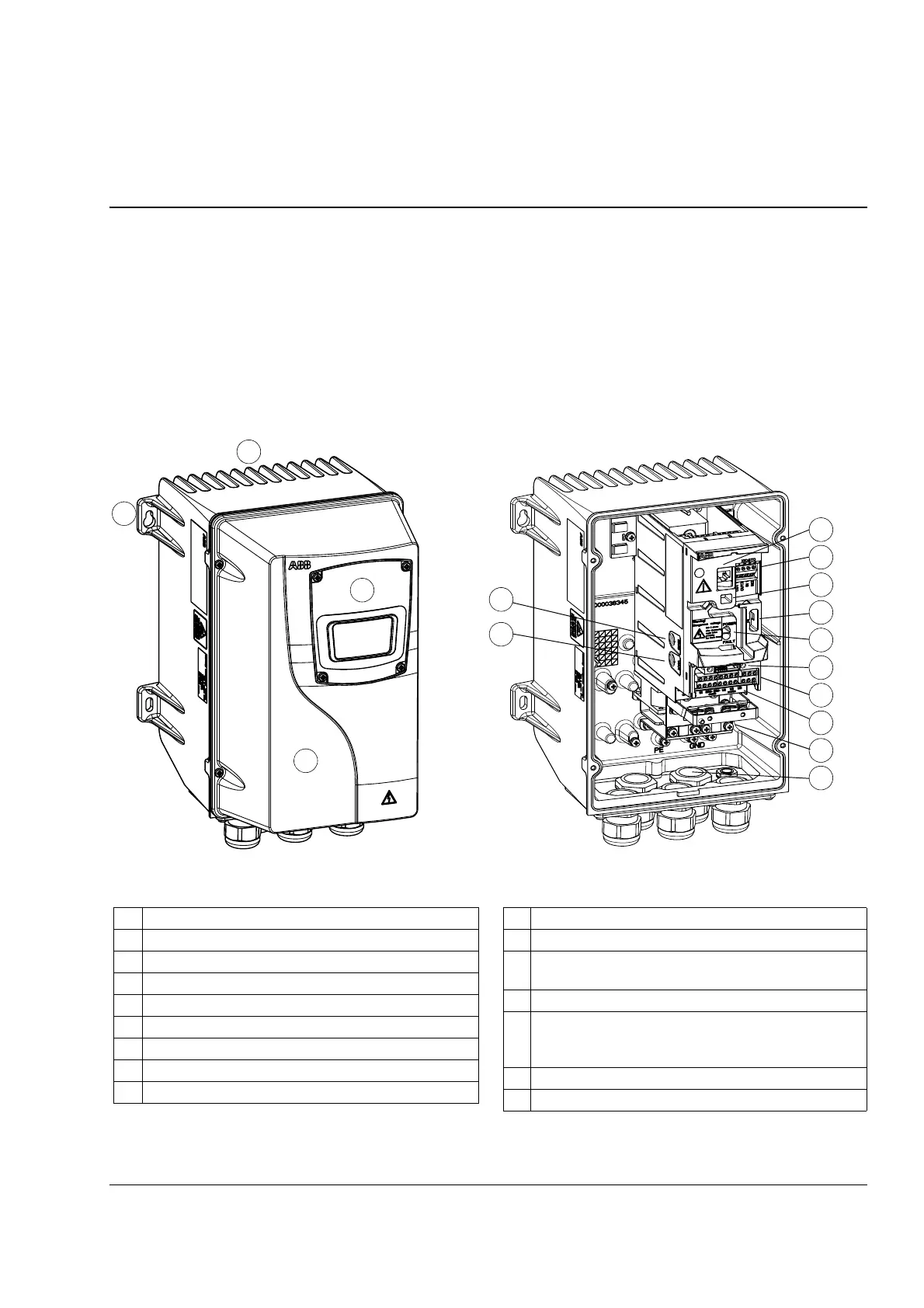
10 FlashDrop connection
11 Power OK and Fault LEDs
12 Fieldbus adapter (serial communication module)
connection
13 I/O connections
14 Input power connection (U1, V1, W1), brake resistor
connection (BRK+, BRK-) and motor connection (U2,
V2, W2)
15 Clamping plate
16 Cable glands
1 Cooling element
2 Mounting holes
3 Control Panel
4 Front cover
5 EMC filter grounding screw (EMC).
6 Varistor grounding screw (VAR)
7 Panel connection
8 Safe torque off connection
9 Option connection
Covers off (R1)Covers on (R1)
1
2
3
4
5
7
10
9
6
12
13
14
15
16
11
8

 Loading...


