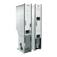
■ Connection procedure (frames R1i…R4i)
WARNING!
Read the safety instructions given in Safety instructions for ACS880
multidrive cabinets and modules (3AUA0000102301 [English]). If you
ignore them, injury or death, or damage to the equipment can occur.
For cabling drawings for each frame size, see Frame R1i...Frames R3i and R4i (connector
covers removed) below.
1.
Stop the drive and do the steps in section Electrical safety precautions (page 112) before
you start the work.
2. Frames R3i and R4i only: Remove the two plastic connector covers at the top and
bottom of the supply module. Each cover is fastened with two screws.
3. On IT (ungrounded) systems and corner grounded TN systems, disconnect the EMC
and varistor screws from the LCL filter module.
• Remove the cover of the LCL filter module.
WFU-11, WFU-21 and WFU-22 only: Remove the fan.
• Remove the two screws labeled FILTER and one screw labeled VARISTOR. The
locations of the screws are shown in the pictures below.
• Reinstall the cover.
WFU-11, WFU-21 and WFU-22 only: Reinstall the fan.
Electrical installation 121
Connection procedure (frames R1i…R4i)
WARNING! Repeat the steps described in section Electrical safety
precautions on page 114. The complete safety instructions are given in
Safety instructions for ACS880 multidrive cabinets and modules
(3AUA0000102301 [English]). If you ignore them, physical injury or death, or damage to
the equipment can occur.
For cabling drawings for each frame size, see pages 123…125.
1. Frames R3i and R4i only:
Remove the two plastic connector covers at the top and
bottom of the supply module. Each cover is fastened with two screws.
2. On IT (ungrounded) systems and corner grounded TN systems, disconnect the EMC
and varistor screws from the LCL filter module.
• Remove the cover of the LCL filter module.
WFU-11, WFU-21 and WFU-22 only:
Remove the fan.
• Remove the two screws labeled FILTER and one screw labeled VARISTOR. The
locations of the screws are shown in the pictures below.
• Reinstall the cover.
WFU-11, WFU-21 and WFU-22 only:
Reinstall the fan.
Note: When the internal EMC filter is disconnected, the IGBT supply module is not EMC
compatible.
WFU-01, WFU-02
Filter1
Varistor2
118 Electrical installation

 Loading...