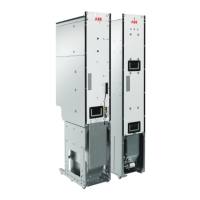
Main contactor
A main contactor is needed for the following reasons:
• If the filter module is connected to the AC input power supply while the
supply/regenerative rectifier module is not modulating/active, there is a risk that the filter
responds to disturbance frequencies in a distorted AC input and starts resonating, which
may cause permanent damage to the supply/rectifier module, filter and equipment
connected to the DC bus. If the supply/rectifier module is stopped, faulty or otherwise
inactive, it cannot counteract the resonance of the filter.
• The supply/rectifier module and the filter module cannot prevent power flow from the
AC input to the DC bus and further to the ACS880-104 inverter module(s). Even if the
modulation of the supply/rectifier module is stopped, the anti-parallel diodes in it enable
power flow to the DC bus and to the inverter(s). In other words, merely stopping the
supply/rectifier module does not stop the system.
• The supply/rectifier module is not protected against excessive current drawn from the
DC bus. If the motoring power (power demanded from the DC bus) exceeds the supplying
capability of the supply/rectifier module, it trips. If the current demand remains or
increases, the supply/rectifier module is damaged.
See also Electrical planning instructions for ACS880 multidrive cabinets and modules
(3AUA0000102324 [English]).
Checking the charging capacity (frames R1i…R4i)
IGBT supply modules of frames R1i…R4i have internal charging circuit. When the power
is switched on in the common DC system, the DC link capacitors in each inverter and supply
module are charged. The charging current is fed through the supply module(s) connected
to the AC. Due to this, the charging capacity of the supply module(s) has to be checked.
The ACS880 inverter and supply modules of frame sizes R1i…R4i have a charging circuit
in series with the capacitor bank.
• In common DC connection, the charging circuits act in parallel.
• The sum of the charging currents is fed from the supply.
Note:
IGBT supply modules of frames R1i…R4i are allowed to be used only with inverter modules
that have charging circuit (eg, ABB inverter modules ACS880-104).
The charging circuit data for each IGBT supply module (ACS880-204) and inverter module
(ACS880-104) are shown in the following tables.
R
min
RFrameACS880-204-
ohmohm
2550R1i006A6-5008A0-3
20130R2i0015A-50018A-3
1566R3i0029A-50035A-3
1066R3i0041A-50050A-3
533R4i0077A-50093A-3
Electrical installation 139

 Loading...