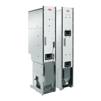
■ Frame R6i
The switching, disconnecting and protecting equipment can be placed inside the drive
cabinet in the following way:
1. The AC supply coming to the drive cabinet is first connected to the main
switch-disconnector [Q1] containing AC fuses.
2. The drive is equipped with the main contactor connected between the main
switch-disconnector [Q1] and the LCL filter.
3. A charging circuit for precharging the DC link capacitors is connected over the main
switch-disconnector [Q1] and the main contactor [Q2]. See section Single-line circuit
diagrams of the supply unit.
For the connection diagram, see the electrical installation chapter.
■ Frame R8i
The switching, disconnecting and protecting equipment can be placed outside the drive
cabinet in the following way:
1. The AC supply is first connected to the main switch-disconnector or main breaker [Q1].
2. The AC fuses are connected after the switch-disconnector.
3. The main contactor [Q2] is connected between the AC fuses and the LCL filter.
4. A charging circuit for precharging the DC link capacitors is connected over the main
contactor [Q2]. See section Single-line circuit diagrams of the supply unit.
For the connection diagram, see the electrical installation chapter.
52 Cabinet construction

 Loading...