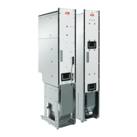
■ LCL filter module (type BLCL-1x-x for frame 1×R8i)
38 Operation principle and hardware description
LCL filter module (type BLCL-1x-x for frame 1×R8i)
Description
A LCL filter module, front
B LCL filter module, back
1. Input (AC) connection
2. Output (AC) connection
3. Terminal block [X55] (power supply for module heating element, option +C183; direct-on-line fan
supply, option +C188) (ready-connected)
4. Handle
5. Fan
6. Wheels
7. Fiber optic connections and LEDs of the BDFC board
8. Terminal block [X30] (power supply for module direct-on-line fan, option +C188 and heating element,
option +C183; module thermal cutoff circuit)
9. Type designation label
10. The unpainted grounding point (PE)
A B
6
2
4
5
1
3
7
8
9
10
LCL filter module, frontA
LCL filter module, backB
Input (AC) connection1.
Output (AC) connection2.
Terminal block [X55] (power supply for module heating element, option +C183; direct-on-line fan supply,
option +C188) (ready-connected)
3.
Handle4.
Fan5.
Wheels6.
Fiber optic connections and LEDs of the BDFC board7.
Terminal block [X30] (power supply for module direct-on-line fan, option +C188 and heating element,
option +C183; module thermal cutoff circuit)
8.
Type designation label9.
The unpainted grounding point (PE)10.
Operation principle and hardware description 37

 Loading...