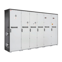
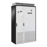
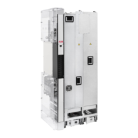
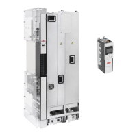
Overview diagram of the drive system
The following figure shows an example drive with a diode supply unit and three inverter
units.
Main circuit breaker [Q1]1
AC fuses2
Supply module [T01] (including choke and rectifier)3
Supply module DC fuses4
Inverter module DC fuses (with or without DC switches)5
Inverter module [T11]6
Motor7
Auxiliary voltage switch [Q21] (option +G344 or +G451)8
Auxiliary voltage transformer [T21] (option +G344)9
16 Operation principle and hardware description

 Loading...


