____________________________________________________________________________________________________________
V2 AC500 Hardware 1-36 System data AC500 / Issued: 05.2007
With connecting the terminals 1-2 and 3-4, a pull-up and a pull-down resistor can be activated (see
chapter "Serial interface COM1” for details).
Wiring
Bus line
Construction
2 cores, twisted,
with common shield
Conductor cross section > 0.22 mm² (24 AWG)
- recommendation 0.5 mm² corresponds to Ø 0.8 mm
Twisting rate > 10 per meter (symmetrically twisted)
Core insulation Polyethylene (PE)
Resistance per core < 100 Ω/km
Characteristic impedance ca. 120 Ω (100...150 Ω)
Capacitance between the cores < 55 nF/km (if higher, the max. bus length must
be reduced)
Terminating resistors 120 Ω ¼ W at both line ends
Commonly used telephone cables with PE
insulation and a core diameter of >
0.8 mm are
normally good.
Remarks
Cables with PVC core insulation and a core
diameter of 0.8 mm can be used up to a length of
ca. 250 m. In this case, the bus terminating
resistor is ca. 100
Ω.
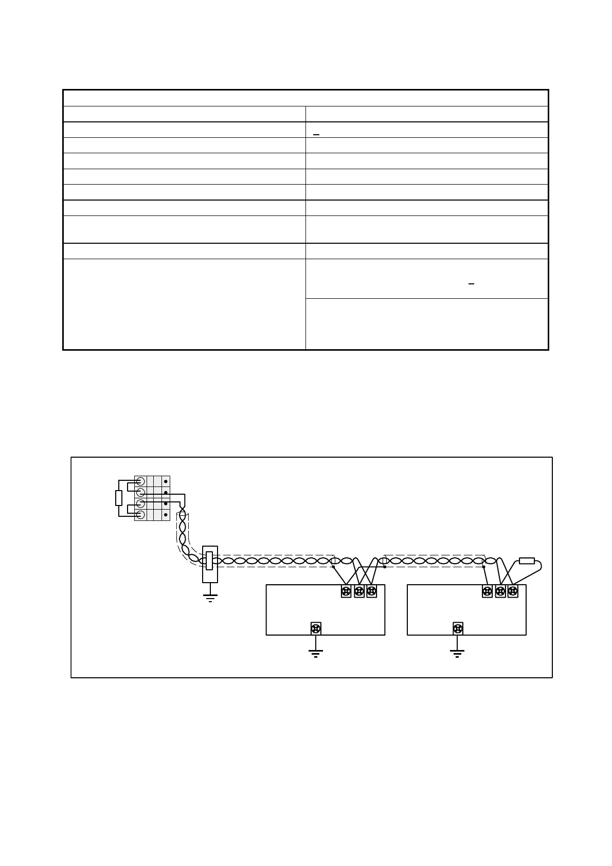
Bus topology
A CS31 system bus always contains only one bus master (CPU or coupler) which controls all actions on
the bus. Up to 31 slaves can be connected to the bus, e.g. remote modules or slave-configured CPUs.
Besides the wiring instructions shown below, the wiring and earthing instructions provided with the
descriptions of the modules are valid additionally.
CS31 system bus
CS31
CS31 bus master
Shield
BUS 2
BUS 1
Shield
BUS 2
BUS 1
slave
CS31
slave
120
Ohms
direct earthing
with clip
on cabinet
steel plate
e.g. PM581
Master at the
bus line end,
pull-up and
pull-down
activated
bus termination
120 Ohms
1
2
3
4
120
Ohms
COM1
Figure: Bus topology for a CS31 system bus at COM1 (bus master at one end of the bus line)