____________________________________________________________________________________________________________
V2 AC500 Hardware 1-56 System data AC500 / Issued: 05.2007
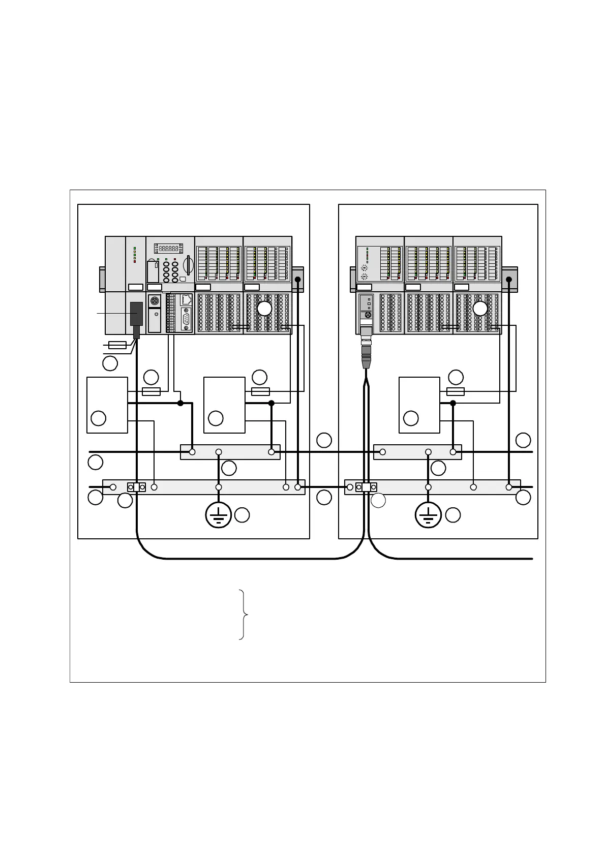
Equipotential bonding
• Install sufficiently dimensioned equipotential bondings, if potential differences are present or have to
be expected in your application between different parts of the installation.
• The impedance of a equipotential bonding must be equal or lower than 10 % of the shield
impedance of the shielded signal cables between the same points.
• The conductor cross section of a equipotential bonding must be able to withstand the maximum
possible compensating current. By experience, a conductor cross section of 16 mm² has proven to
be sufficient.
• Equipotential bondings and shielded signal cables should be laid close to each other. This prevents
coming up inductive loops in which disturbances could be induced.
• Equipotential bondings must be connected to PE with low impedance.
DX522DC532 DX522DC532
AC500 S500
24V
DC
+
–
PE
Cabinet 1 Cabinet 2
24V
DC
+
–
PE
3
7
10
11
6
5 5
8
9 9
11
DIN rail
1 24V power supply FBP
2 Power supply for the CPU
6 For fuses for the contacts of the relay outputs
see the descriptions of the relevant modules
8 Earthing of the 0V rail
9 Cabinet earthing
10 Equipotential bonding
between the cabinets min. 16 mm
11 Cable shields earthing
2
1010
8
6
24V
DC
+
–
PE
7
7
0V 0V
PE PE
DC505
24V
0V
1
2 4
5 Fuse for the I/O modules power
3 Fuse for the CPU power
4 Power supply for the I/Os
only one power
possible
supply is also
7 0V rail (reference potential for signals)
with terminating resistor
4
Figure: AC500, equipotential bondings