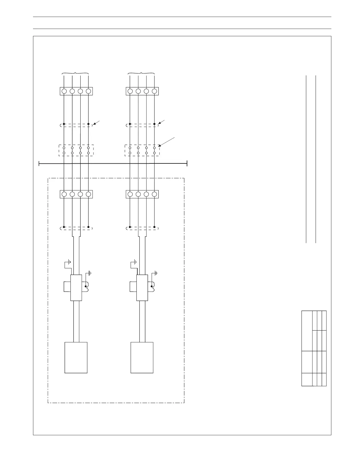
Fig. 5.3 AK101 Low Flow Alarm Option System Diagram
Note 1: Apparatus which is unspecified except that it must not be supplied from
nor contain in normal or abnormal conditions a source of potential with
respect to earth in excess of 250 volts r.m.s or 250 volts d.c.
Note 2: The maximum capacitance and the maximum inductance of the
Hazardous Area Cables shall comply with the following:
Cc <= Ca – Ci
Lc <= La – Li
Where:-
Cc = The maximum permitted capacitance of the Hazardous Area Cables.
Ci = The terminal capacitance of the GIR Floscan Alarm (Ci – 133.1nF)
Ca = The maximum value of capacitance that is permitted by the barrier
And:-
Lc = The maximum permitted inductance of the Hazardous Area Cables
Li = The terminal inductance of the GIR Floscan Alarm (Li = 0
μ
H).
La = The maximum value of inductance that is permitted by the barrier.
Note 3: The capacitance and either the inductance or the inductance to resistance
(L/R) ratio of the cable connected between terminals 3 & 4 of MTL 767+
Zener diode safety barrier and terminals 3 & 4 of a GIR sensor terminal box
on Katharometer panel must not exceed the following values:-
Group
Capacitance
in μF
Inductance
in mH
L/R ratio
in μH/Ohm
IIC
IIB
IIA
0.58
3.55
14
1.45
7.22
14
66
263
544
or
Safe Ar
Circuit A
ea
Floscan
Relay Module
Safe area apparatus
See Note 1
See Note 6
Screen
Red
White
Black
I.S. Earth
Zener Diode
Safety Barrier: MTL 767+
CERT No BAS 01 ATEX 7202
IEC Ex BAS 05.0019
Hazardous Area
1
4
2
3
Junction boxes (if required) see note 7.
Location: Hazardous or Safe Area
16
14
15
16
Screen
TB
JB
Terminal Box
See Note 5
GIR
Low
Flow
Sensor
Red
White
Black
1
3
4
2
Circuit B
Floscan
Relay Module
See Note 6
B4
B5
Screen
Red
White
Black
I.S. Earth
Zener Diode
Safety Barrier: MTL 767+
CERT No BAS 01 ATEX 7202
IEC Ex BAS 05.0019
1
4
2
3
17
18
19
17
Screen
TB
JB
Terminal Box
See Note 5
GIR
Low
Flow
Sensor
Red
White
Black
1
3
4
2
Note 4: The cables may be separate cables or may be installed as separate circuits
within a Type ‘A’ or a Type ‘B’ multicore cable as defined in EN60079-25 (latest edition)
subject to the following:-
a: Each circuit shall be individually screened within a Type ‘A’ Multicore Cable
b: The peak voltage of any other circuit within a Type ‘B’ Multicore Cable must not
exceed 60 volts.
Note 5: The installation must comply with the national requirements.
(e.g. within the UK the standard EN60079-14: (latest edition) is used).
Note 6: The system must be marked with a durable label, the label should appear on or
adjacent to the principle item of electrical apparatus in the system or at the
interface between the intrinsically safe and non-intrinsically safe circuits.
Note 7: A junction box if used, must satisfy the requirements of clauses 6.1 and 6.3.1
of EN60079:11 (latest edition).
See Notes 2, 3 & 4 for cable details
See Notes 2, 3 & 4 for cable details
+12V
S
1
+12V
S
1
Note. This drawing applicable only if Low Flow Sensors are fitted.