18
External
power supply
TB1
1
2
3
4
5
6
7
8
9
10
Katharometer
Unit Gas Panel 2
%H
2
and Air
in Purge Gas
TB1
1
2
3
4
5
6
7
8
9
10
Katharometer
Unit
Gas Panel 1
(H
2
in Air)
TB1
TB2
Power Supply Unit 2
4234
LN
E
TB1
TB2
Power Supply Unit 1
4234
LN
E
External
power supply
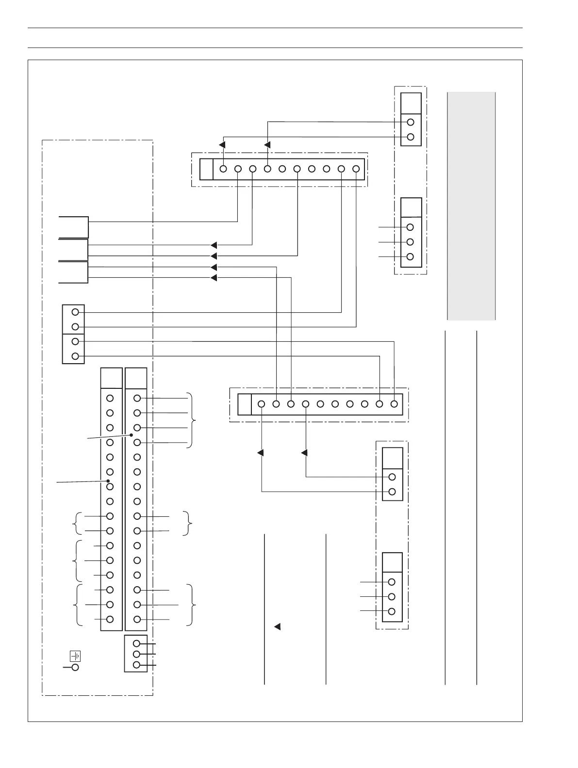
Note. Interconnections
marked with
MUST conform to th
e
intrinsically safe wiring requirements
given in the text.
All other wiring to suit power and signal
requirements
+
–
+ –
Zener diode safety
barrier devices
Connections for Lower Display
Connections for Upper Display
L N E
12345678910
11 12 13 14 15 16
TB4
NO
NC
COM
Remote
Range
(AK101 only)
H
2
in Purge Gas*
or
Air in Purge Gas*
Alarm 1
Purge Gas Value
Retransmission
+ –
12345678910111213141516
External bonding
and earth
TB3
Monitor
17 18 19 20
B1
4 3
B2
4 3
TB5 TB6
TB2
Note.
Katharometer Gas Unit Panel 1 is connected internally within 6553 Gas Monitor to Upper Display.
Katharometer Gas Unit Panel 2 is connected internally within 6553 Gas Monitor to Lower Display.
MTL 7755ac
NO
NC
COM
Alarm 1
H
2
in Air
NO
NC
COM
Alarm 2
H
2
in Air
H
2
in Air Value
Retransmit
B3
4 3
+
+
–
–
–
+
–
Common
Range 3
Range 2
Range 1
+
–
...5 ELECTRICAL INSTALLATION
Fig. 5.6 Interconnection Wiring Diagram – AK101 Intrinsically Safe Analyzer System (Hydrogen Purity and Purge Gas)
*Note. Purge gas options include:
CO
2
(Carbon dioxide)
N
2
(Nitrogen)
Ar (Argon)