8
…2 MECHANICAL INSTALLATION
11
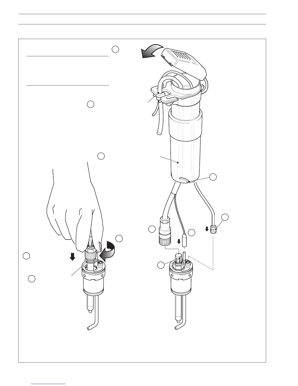
Close cover
Locate cable shroud over
sensor holder and twist
clockwise to engage
bayonet lugs in slots
9
Clip cables and jetwash tube
(if required) into slots in
protective cover
1
Route cables and jetwash tube
(if required) through cable shroud
Tighten
Locate sensor
cable connector
over keyway
Connect earth
(ground)
terminal
to rod
8
Connect jetwash
supply tube
(if required –
see Section 2.5)
and tighten to
recommended
torque value of
60cNm
Ensure support washer
and O-ring are fitted to
electrode
2
4
6
3
Insert sensor in holder
Tighten to
recommended
torque value of
125cNm
7
5
10
Fig. 2.6 System Assembly
Note. Model AP201 shown. When
assembling Models AP202 and AP203,
refit the Tee piece to the sensor holder
(AP202) or the sensor guard to the dip
tube (AP203) – see Figs. 2.4 and 2.5.
2.3 System Assembly – Fig 2.6

 Loading...


