12
…3 ELECTRICAL INSTALLATION
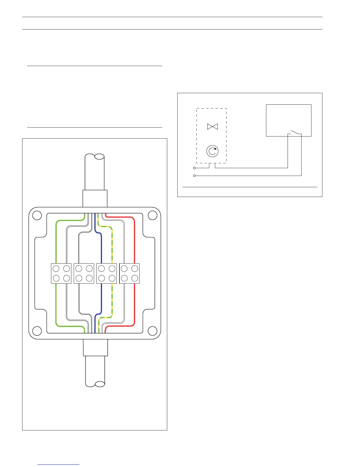
3.3 Extending the Connection Cable – Fig. 3.3
If it is necessary to extend the cable, a suitable junction box and
the correct length of 6-core cable are required. Connect the
junction box as shown in Fig. 3.3.
Notes.
• Junction box (part no. 7690/049) is recommended.
• 6-core cable, part no, AA101/0XX (where XX is the
cable length, from 0.5 to 50 meters, in increments of
0.5 meters) is recommended.
• Cable AA101/0XX is identical to that fitted to the
sensor. See Fig. 3.2 for cable end preparation
instructions.
Transmitter
Auto Clean
Relay Contact
OR
Pump
Solenoid
Valve
N/O C
Fig. 3.4 Electrical Connections for Jetwash Systems
Fig. 3.3 Extending the Connection Cable
3.4 Jetwash System Connections
The electrical supply to the jetwash system pump or solenoid
valve is connected to the analyzer relay used for automatic
cleaning – see Fig. 3.4. The analyzer controls the frequency of
the wash sequence and the duration for which the cleaning
solution flows.
The analyzer outputs are held during a cleaning sequence.
Cable from AP200 Sensor
Extension Cable
(Pt No. AA101/0XX)
to Analyzer
Green
White
Grey
Red
Green/Yellow
Green
Grey
White
Blue
Green/Yellow
Transparent
Red
Transparent
Junction Box
Pt No. 7690/049
Blue

 Loading...


