9
Twin Wash Nozzles
Maintenance
Cleaning
Screw
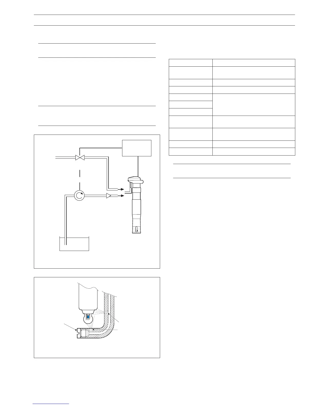
Fig. 2.7 Typical Jetwash Installation
Fig. 2.8 Location of Jetwash Nozzle
gnitaoCtnegAgninaelC
sliOdnaesaerG
stnevloselbulos-retawrostnegretedenilaklA
slohoclasahcus
sniseRsilaklaetuliD
setanobraC/enotsemiLdicacirtinM1
sedixordyhlateM
dicacirtinrociruhplusM1sedinayC
lacigoloibyvaeH
snietorP
dnadicacirtinrociruhplusM1foerutxiM
)detarutas(nispep
serbiF
gnittewtuohtiwrohtiwretawdezirusserP
stnega
lacigoloibthgiLretawdezirusserP
)wolebetoNees(xetaLretawdlocdezirusserP
Mains water
or
Pressurized
cleaning
solution
Transmitter
with autoclean
relay contact
Solenoid
Valve
Pump
Reservoir
(water or
cleaning
solution)
OR
Use a non-
return valve
to maintain
optimum
performance
2.4 Jetwash System – Figs 2.6 to 2.8
Note. Installation must be carried out in accordance
with local water company and council bylaws.
The jetwash system enables automatic cleaning of both the
measuring element and the reference junction by spraying either
water or a cleaning solution at them in situ, thus reducing system
maintenance requirements.
An external pump or solenoid valve is required, controlled by a
pH analyzer with auto-cleaning control functions.
Note. For optimal performance, the pressure of the
jetwash system should be 2 to 3 bar (30 to 45 psi)
greater than the process pressure.
2 MECHANICAL INSTALLATION…
Note. If removed from the process the latex must be
completely removed quickly before it hardens.
Cleaning Solutions
The spray jet tube is available in 316 stainless steel. Some typical
cleaning solutions are:
 Loading...


