4
To ensure electrode
is always in sample
Isolating
Valve
Isolating
Valve
ø50
Rp 1 in.
Female Threads
Typical Installation
314
(12.36)
95
(3.74)
100
(3.94)
147
(5.79)
To prevent spillage
when system
is removed
90
(3.54)
76
(3)
(Polypropylene
versions only)
(Stainless Steel
versions only)
100
(3.94)
Minimum
clearance
required
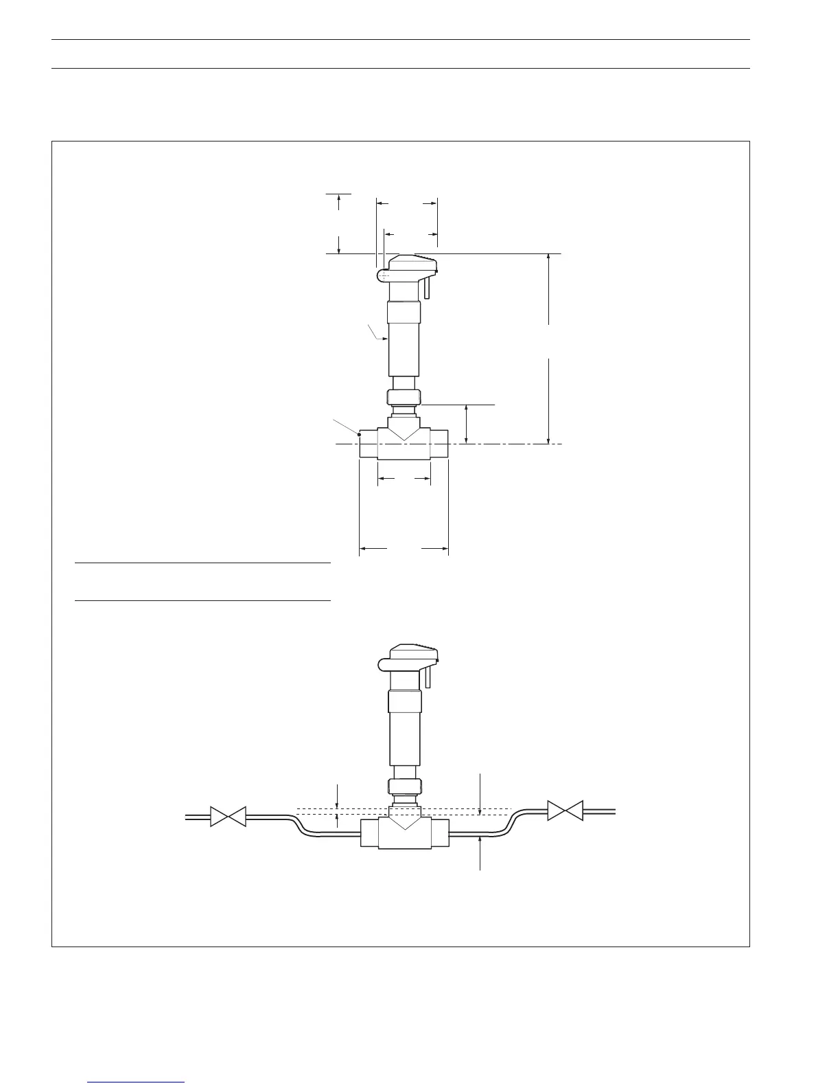
Fig. 2.2 Model AP202 Inline System
…2 MECHANICAL INSTALLATION
2.1.2 Model AP202 Inline System – Fig. 2.2
This system is supplied with an inline tee-piece for mounting the system directly into a pipeline. Allow sufficient height above the
system to enable the sensor to be withdrawn from the tee-piece.
Dimensions in mm (in.)
Note. Refer to Section 6 – SPECIFICATION
for information about the different versions.

 Loading...


