3
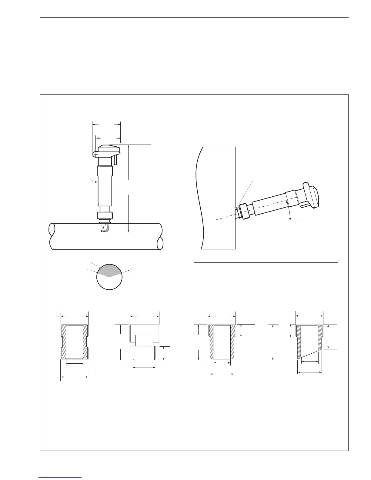
Fig. 2.1 Model AP201 Insertion System
Pipe-Mount System
Tank-Mount System
ø50
327
(12.87)
100
(3.94)
15° min. from horizontal
Angled-Weld Socket
Allowable Mounting Position
15° min.
15° min.
90
(3.54)
G 1
1
/
4
G 1
1
/
4
G 1
1
/
4
R 1
1
/
4
ø25
50
(1.97)
40
(1.58)
ø25
ø36
ø25
ø36
1 in. NPT
or R 1in.
20
(0.78)
Mounting Adaptors
18
(0.71)
G 1
1
/
4
or
1
1
/
4 NPT
18
(0.71)
50
(1.97)
50
(1.97)
7690 130
PPS Ryton R1
1
/
4
in. Adaptor
+
7690 134
PP 1
1
/
4
in. NPT Adaptor
+
7690 129
PP R1
1
/
4
in. Adaptor
7690 131
1in. NPT Stainless Steel
Mounting Adapter
+
7690 128
R1in. Stainless Steel
Adaptor
7690 132
DN25 Straight-Weld Socket
(316 SS)
7690 133
DN25 Angled-Weld Socket
(316 SS)
2 MECHANICAL INSTALLATION
Note. When installing the Model AP201 insertion system,
ensure that the electrode is fully immersed in sample
under all operating conditions.
Dimensions in mm (in.)
2.1 Installing the Systems
2.1.1 Model AP201 Insertion System – Fig. 2.1
This system is designed to mount directly into a pipeline or tank. Mounting adaptors are available:
7690 130 PPS Ryton™ R 1
1
/4 in. adaptor 7690 128 R 1in. Stainless Steel adaptor
7690 134 Polypropylene 1
1
/4 in. NPT adaptor 7690 132 DN25 Straight-weld socket
7690 129 Polypropylene R 1
1
/4 in. adaptor 7690 133 DN25 Angled-weld socket
7690 131 1in. NPT Stainless steel adaptor

 Loading...


