Functional Software description
DCS 500 Software Description 47
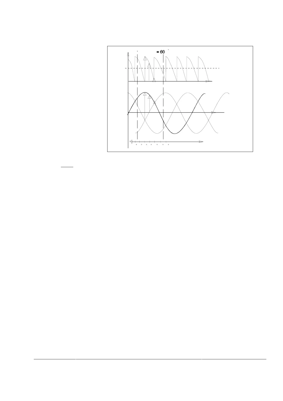
Firing angle ex-
ample
L1 L2 L3
t
U
output voltage
main voltage
firing angle
average voltage
0 30 60 90 120 150 180
α
Figure 23 Armature voltage controlled by firing angle 60
°
Note. To avoid shooting through of the converter, the adjusted val-
ues of alpha limits should not be changed without consulting
ABB.
Status Indication
for Bridge
Output connection point ARM DIR (10402) from the firing unit indi-
cates the bridge in use:
0 = no bridge, 1 = motor bridge, -1 = generator bridge.
Values of the U MOTN V (501), I MOTN A (502) and U SUPPLY
(507) must be given to the program, because these parameters are
used for scaling the actual values of e.g. armature current.