17DC Drives 17DC Drives
english
—
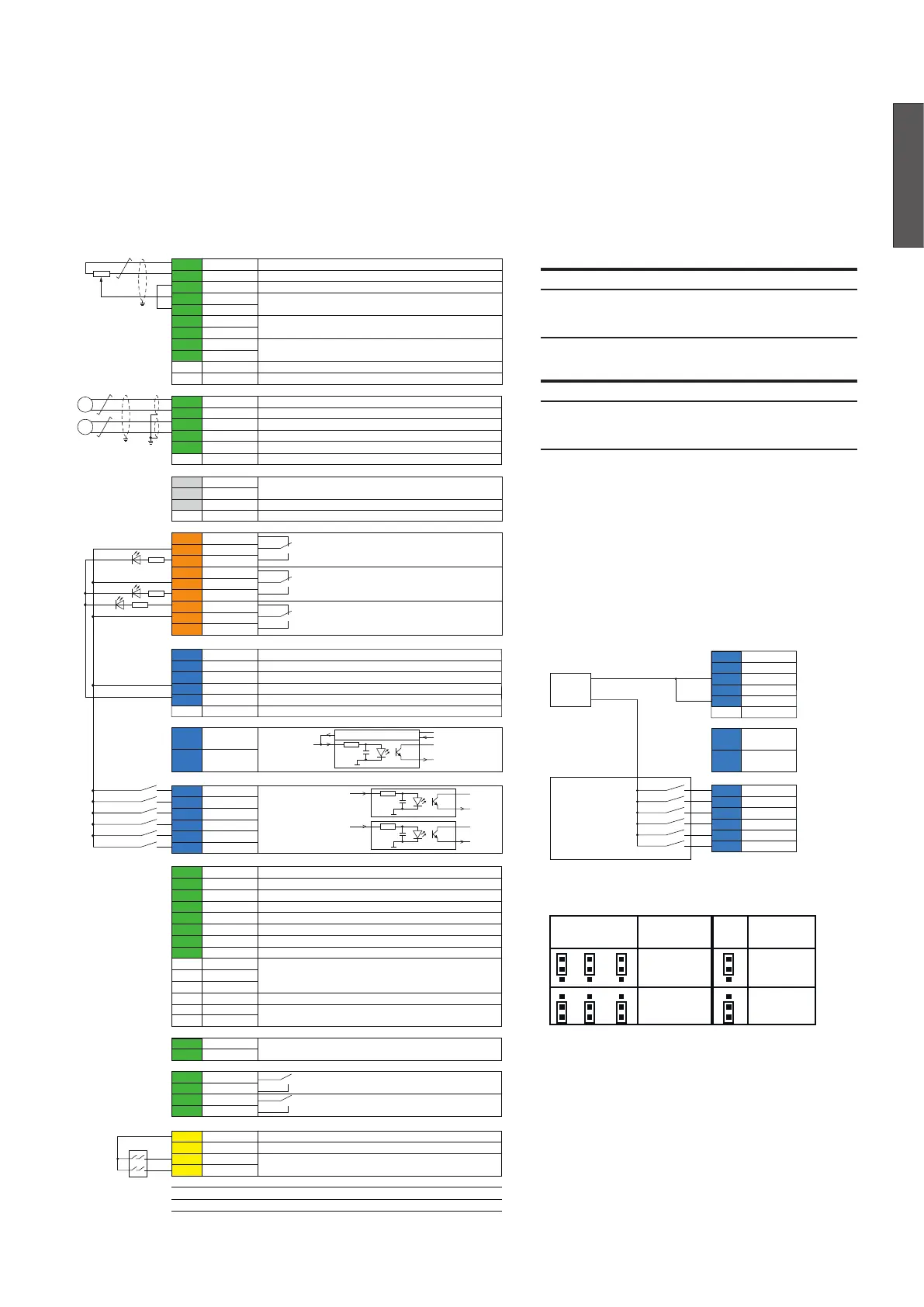
Control circuit terminal layout
Relay driver
2k
+24 V
DC
+3.3 V
DC
max. +24 V
DC
DO
DI
100n
DIOGND
2k
+3.3 V
DC
max. +24 V
DC
DI1 ... DI5 and DIL
DI
100n
DICOM
2k
+3.3 V
DC
max. +24 V
DC
DI6
DI
100n
DIOGND
XAI Reference voltage and analog inputs
1 +VREF +10 V
DC
2 -VREF -10 V
DC
3 AGND Common ground (connected to frame)
4 AI1+ ±10 V or 0 (4) ... 20 mA depending on J1
5 AI1-
6 AI2+ ±10 V or 0 (4) ... 20 mA depending on J2
7 AI2-
8 AI3+ ±10 V
9 AI3-
J1 J1 AI1 current / voltage selection jumper
J2 J2 AI2 current / voltage selection jumper
XAO Analog outputs
1 AO1 ±10 V or 0 (4) ... 20 mA depending on J5
2 AGND Common ground (connected to frame)
3 AO2 ±10 V
4 AGND Common ground (connected to frame)
5 IACT Connection point for a scope (H1 ... H6 only)
J5 J5 AO1 current / voltage selection switch
XD2D Drive-to-drive link
1 B Drive-to-drive link
2 A (master-follower or embedded fieldbus)
3 BGND Isolated ground 2
J3 J3 Drive-to-drive link termination switch
XRO1, XRO2, XRO3 Relay outputs
11 NC
12 COM 250 V
AC
/ 30 V
DC
13 NO 2 A
21 NC
22 COM 250 V
AC
/ 30 V
DC
23 NO 2 A
31 NC
32 COM 250 V
AC
/ 30 V
DC
33 NO 2 A
XD24 Digital interlock
1 DIL Digital interlock, ground: DICOM
2 +24VD +24 V
DC
, 200 mA, ground : DIOGND
3 DICOM Isolated digital input ground for DI1 ... DI5 and DIL
4 +24VD +24 V
DC
, 200 mA, ground : DIOGND
5 DIOGND Isolated digital input / output ground for DI6, DIO1, DIO2
J6 J6 Digital ground selection switch (DIOGND and DICOM)
XDIO Digital inputs / outputs
1 DIO1
2 DIO2
XDI Digital inputs
1 DI1
2 DI2
3 DI3
4 DI4
5 DI5
6 DI6
XENC Encoder
1 A+ Channel A+ function depending on J4A
2 A- Channel A- function depending on J4A
3 B+ Channel B+ function depending on J4B
4 B- Channel B- function depending on J4B
5 Z+ Channel Z+ function depending on J4C
6 Z- Channel Z- function depending on J4C
7 EGND Common ground (connected to frame)
8 +VENC Encoder supply 5 V
DC
or 24 V
DC
depending on J4D, 250 mA
J4A J4A Differential or single ended (10 k pull up)
J4B J4B selection jumpers
J4C J4C
J4D J4D Encoder supply 5 V
DC
or 24 V
DC
selection jumper
J7A J7A Not in use for DCS880
J7B J7B
XTAC Analog tacho
1 AITACH+ ±8 … 270 V
DC
2 AITACH-
XSMC Mains contactor
1 MCCOM 250 V
AC
/ 30 V
DC
Fixed output for the mains
2 MCNO 2 A contactor
3 STOCOM 250 V
AC
/ 30 V
DC
Fixed output for safe torque
4 STONO 2 A off (STO) zero current monitor
XSTO Safe torque off (STO)
1 OUT1 24 V
DC
for STO circuit
2 SGND Common ground (connected to frame)
3 IN1 Both circuits must be closed for drive to start
4 IN2 Open circuits block the firing pulses
X12 Safety functions module connection
X13 Control panel connection
X205 Memory unit connection
For H7 and H8 see SDCS-OPL-H01.
SA_880_005_DCS_d.ai
DCS880
Safety
relais
Control cables:
Wire sizes: Tightening torques:
for both, stranded and
solid wiring
Wire sizes: Tightening torques:
for both, stranded and
solid wiring
External 24 V
DC
used
XD24 Digital interlock
1 DIL
2 +24VD
3 DICOM
4 +24VD
5 DIOGND
J6 J6
XDIO Digital input / outputs
1 DIO1
2 DIO2
XDI Digital inputs
1 DI1
2 DI2
3 DI3
4 DI4
5 DI5
6 DI6
Power
supply
PLC
0 V
DC
24 V
DC
default
default
J4
A B C
J4
D
Encoder
supply
10 kΩ 24 V
5 V
120 Ω
pull up
differential