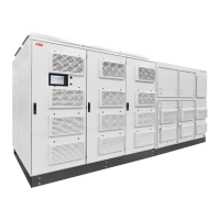
Modifications reserved
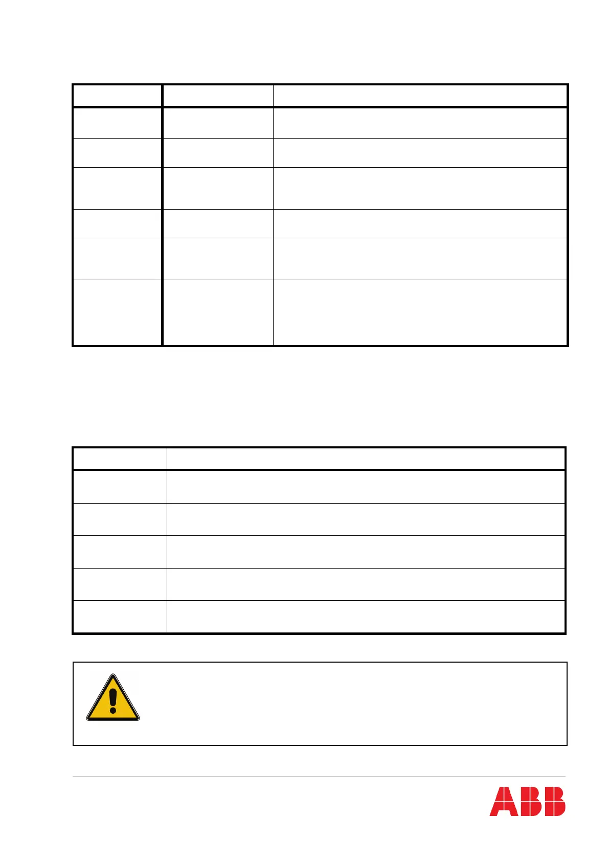
The ALARM LED indicator is a visual indication of any internal or external alarm condition. At the same
time, an audible alarm will be activated.
INDICATOR INDICATOR STATUS MEANING
ALARM
OFF
RED
No alarm condition
Alarm condition
LINE 1
GREEN
RED
Mains rectifier available
Mains rectifier not available
LINE 2
GREEN
RED
OFF
Mains bypass available
Mains bypass not OK or not available
UPS is turned off
BYPASS
GREEN
OFF
Load on bypass (bypass-or eco-mode)
Bypass not operating (switched-off)
INV
GREEN
RED
OFF
Load on inverter
Inverter fault or load not transferable to inverter
Inverter not operating (switched-off)
BATTERY
OFF
GREEN
RED
Flashing GREEN
Flashing RED
UPS is turned off
Battery connected and ok
Fault condition of the battery (alarm)
Battery in discharge
Battery low or disconnected
6.1.2 Buttons
The keys allow the user to perform settings and adjustments, to start up and shut down the UPS and,
using the LCD, to monitor voltages, currents, frequencies and other values.
KEYS FUNCTION
ON/OFF
ON/OFF
Serves to switch-on (press both keys simultaneously), or shut down the UPS (press both keys
simultaneously)
UP () Move upwards through the menu
DOWN () Move downwards through the menu.
RESET
Cancel the audible alarm. If the alarm condition was only transient the LED-indicator ALARM would also
extinguish otherwise it will remain on (red).
ENTER
Confirms a chosen menu item.
IF A PARALLEL UPS HAS TO BE TURNED OFF, THEN BOTH ON/OFF
BUTTONS ON ALL UPS MODULES HAVE TO BE PUSHED. IN THIS CASE,
THE POWER SUPPLY TO THE LOAD WILL BE INTERRUPTED