52| © 2020 Emax 2 Retrofill Circuit Breakers 600A-4000A 2TSA451011P0000 Rev-B
AK 75 - 3000A, Fan Control Unit Wiring & Trip unit Programming instructions
Wiring Diagram
Follow the below circuit diagram to make the connections between the 2k-1 signalling
unit, relay and fans.
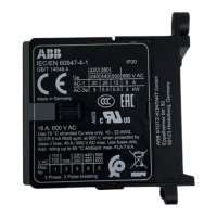
Refer Relay diagram & 1SDH001000R0524 to identify the terminal marking in circuit
diagram.
Note: U1 & U2 Emax 2 motor operator (120 V~) terminal.
NOTE 1: In the absence of motor or if motor voltage rating is different than 120 V~ ,
connect 120 V` directly to T1 and T2
Refer 2TSE432074P1000 and 2TSE432048R1000 for the wire length and lug details.
Figure 96
Figure 97

 Loading...

