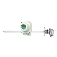
Endura AZ series integral and remote transmitter
Combustion oxygen monitor 4 Electrical Installation
IM/AZ20E–EN Rev. F 15
4.4 Remote Transmitter – Remote AZ10 Sensor Cable Connections
4.4.1 Systems with 5 m (18 ft) Cable Length
Sensor connection Transmitter Connection Cable Color Connection / Note
White / Yellow (not used)
White / Black (not used)
White / Orange (not used)
White / Green (not used)
White / Red (not used)
White / Blue (not used)
White / Yellow (not used)
White / Black (not used)
White / Orange (not used)
White / Green (not used)
White / Red (not used)
White / Blue (not used)
White / Yellow (not used)
White / Black (not used)
White / Orange (not used)
White / Green (not used)
White / Red (not used)
White / Blue (not used)
NOT USED
Cut wires back at
both ends of cable
Red Red Red Cell + (oxygen input)
Black Black Black Cell – (oxygen input)
Violet Violet Violet ACJC
Grey Grey Grey ACJC
Green Green Green T/C +
White White White T/C –
Earth stud (Screen 1 and 2) SCN (not used) Screen 1 and 2 (sleeved) See Fig.
4.4
Brown Brown Brown Heater 1
Blue Blue Blue Heater 2
Tab le 4. 1 System s w it h
5 m (
18 ft) Cable Length
Fig. 4.4 Systems with
5 m (
18 ft) Cable Length
VIOLET
BLACK
RED
WHITE
CELL
–+–+
GREY
GREEN
T/C
ACJC
CELL
T/C
–
+
+
R
W
BL
BLUE
BROWN
GREEN
H1
CLR
CLR
H2
H1 H2
AZ10 sensor*
ACJC (Grey)
ACJC (Violet)
TC+ (Green)
TC– (White)
Cell + (Red)
Cell – (Black)
Screen 1 and 2 drains connected to sensor
internal earth stud only – not to SCN terminal
AZ10 remote transmitter*
Cell + (Red)
Cell – (Black)
ACJC (Violet)
ACJC (Grey)
T/C + (Green)
T/C – (White)
NOT USED
SCN (Screen)
H (Blue) H (Brown)
H (Brown) H (Blue)
Not used – see Table 4.1
Screen 1 and 2 drains at sensor
connected to internal earth stud only
Green (earth wire from
sensor earth stud)
Special ABB 14-core Cable Only:
5 m (18 ft) Length
*Metal gland required at sensor and transmitter

 Loading...