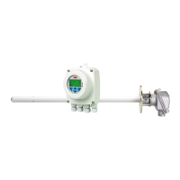
Endura AZ series integral and remote transmitter
Combustion oxygen monitor 4 Electrical Installation
IM/AZ20E–EN Rev. F 17
4.5 Remote Transmitter – Remote AZ20 Probe Cable Connections
Ter m i n al
Number
Tag ID Connection Type Cable Color Code
1HHeater Brown
2HHeater Blue
3 SCN Screen Screens
4T / C –Thermocouple (–ve) White
5 T / C+ Thermocouple (+ve) Green
6 ACJC PT1000 Cold Junction Compensation Grey
7 ACJC PT1000 Cold Junction Compensation Violet
8 CELL – Oxygen Input (–ve) Black
9 CELL + Oxygen Input (+ve) Red
10 PS2 Pressure Switch – Gas 2 White / Yellow
11 P COM Pressure Switch – Common White / Black
12 PS1 Pressure Switch – Gas 1 White / Orange
13 SV2 Solenoid Valve – Gas 2 White / Blue
14 SV COM Solenoid Valve – Common White / Red
15 SV1 Solenoid Valve – Gas 1 White / Green
Table 4.3 Remote Transmitter – Remote AZ20 Probe Cable Connections
Fig. 4.6 Remote Transmitter – Remote AZ20 Probe Cable Connections
9 CELL +
8 CELL
7 ACJC
6 ACJC
5 TC +
4 TC
3 SCN
14
SV COM
12
P1
11
P COM
15
SV1
13
SV2
10
P2
2 H
1 H
To Pro be –
Refer to IM/AZ20P–EN for
Remote Probe Connection Details
AutoCal Connection (Terminals 10 to 15)
Standard
Connection
(Terminals 1 to 9)

 Loading...