F, V, W S e r i e s
Electromagnetic flowmeters | Full-bore flow sensors 4 Specification
OI/FEF/FEV/FEW–EN Rev. D 23
Physical Specification
Wetted parts
Electrode material
Stainless steel 316 L / 316 Ti
Super-austenitic steel
Hastelloy
®
C-22 and Hastelloy
C4
(other electrode materials available on request)
Potential equalizing rings
Minimum of 1 recommended
Lining material / potable water approvals
Lining protection plates
Not required
Installation conditions (recommended)
Pressure loss
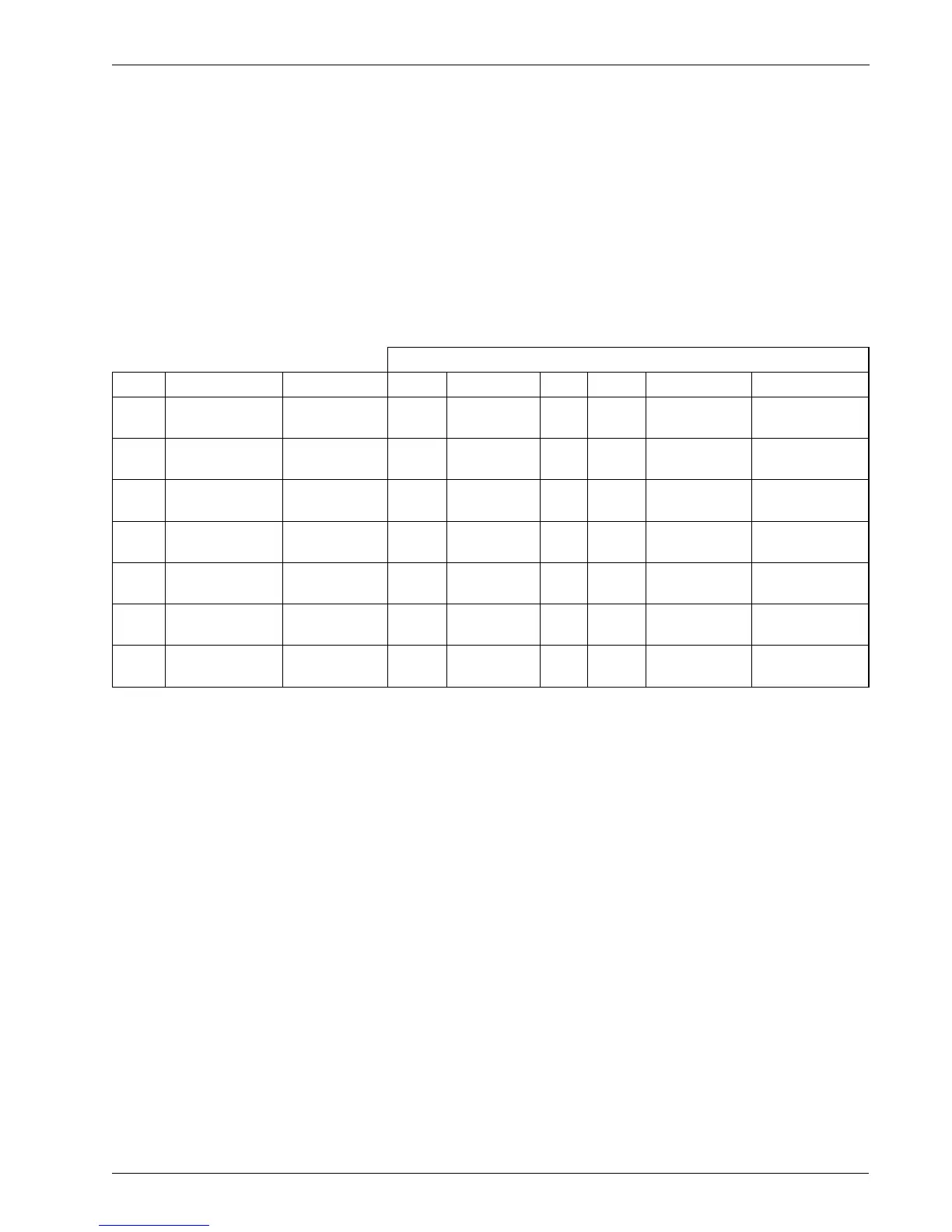
Potable Water Approvals
Code Size Range Liner WRAS WRAS 60°C ACS DVGW NSF AZ/NZS4020
FEW1
DN10 – 32
(
3
/8 – 1
1
/4 in. NB)
PTFE
FEW3
DN10 – 600
(
3
/8 – 24 in. NB)
PTFE
FEW3
DN40 – 2400
(1
1
/2 – 96 in. NB)
Elastomer
FEW3
DN40 – 2400
(1
1
/2 – 96 in. NB)
Hard rubber
NSF approved
material
FEV
DN40 – 200
(1
1
/2 – 8 in. NB)
Polypropylene NSF-61
FEF
DN250 – 600
(10 – 24 in. NB)
Elastomer NSF-61
FEF
DN250 – 600
(10 – 24 in. NB)
Hard rubber
NSF approved
material
*Size is dependent on flange specification
Straight pipe requirements
Upstream Downstream
FEW / FEF 5 x DN 2 x DN
FEV 5 x DN 0 x DN
Negligible at Q3 All full bore meters
<0.25 bar (<3.62 psi) at Q3 FEV (DN40 to 200 [1
1
/2 to 8 in. NB])