1
A
B
C
D
E
F
2 3 4 5 6 7 8
A
B
C
D
E
F
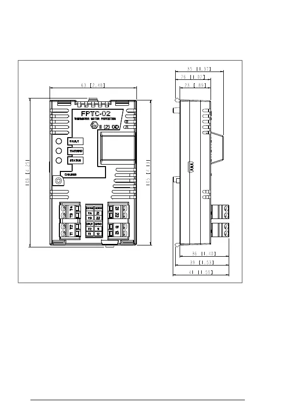
Original drawing made with 3D CAD. Set the correct scale factor when adding dimensions after DWG/DXF conversion.First angle projection.
108 4.25[ ]
105 4.13[ ]
63 2.48[ ]
35 1.37[ ]
41 1.59[ ]
39 1.53[ ]
36 1.40[ ]
16 .61[ ] 32 1.26[ ]
8 .30[ ]50 1.97[ ]47 1.83[ ]
7 .26[ ]
23 .89[ ]
26 1.02[ ]
FPTC_02_DIMENSION_DRAWING 0+
We reserve all rights in this document and in the information contained therein. Reproduction,
use or disclosure to third parties without express authority is strictly forbidden.
© ABB Oy. PROPRIETARY AND SECRET INFORMATION. CONFIDENTIAL
3AXD50000017196 (ASSEM) B.0+
Based on Prepared
J.Diov 24-Jun-15
Title
ASSEMBLY DRAWING
Doc. des. Scale Form
Customer Check.
24-Jun-15
ASSEMBLY DRAWING 1:1 A4
Appr.
24-Jun-15
Resp.dept. Rev.ind.
.0 ()
Lang.
EN
Cust. Doc. No. Project name Doc. No. Sheet
1
DMS Number Weight kg
0.24
Total
3
A
Initial Approval 24-Jun-15 J.Diov
ground. Isolation area C is in the same potential as the PTC sensor