52
Installation and commissioning guide
2750 515-1 EN, REV. 14, 2020-06-26
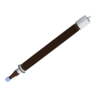
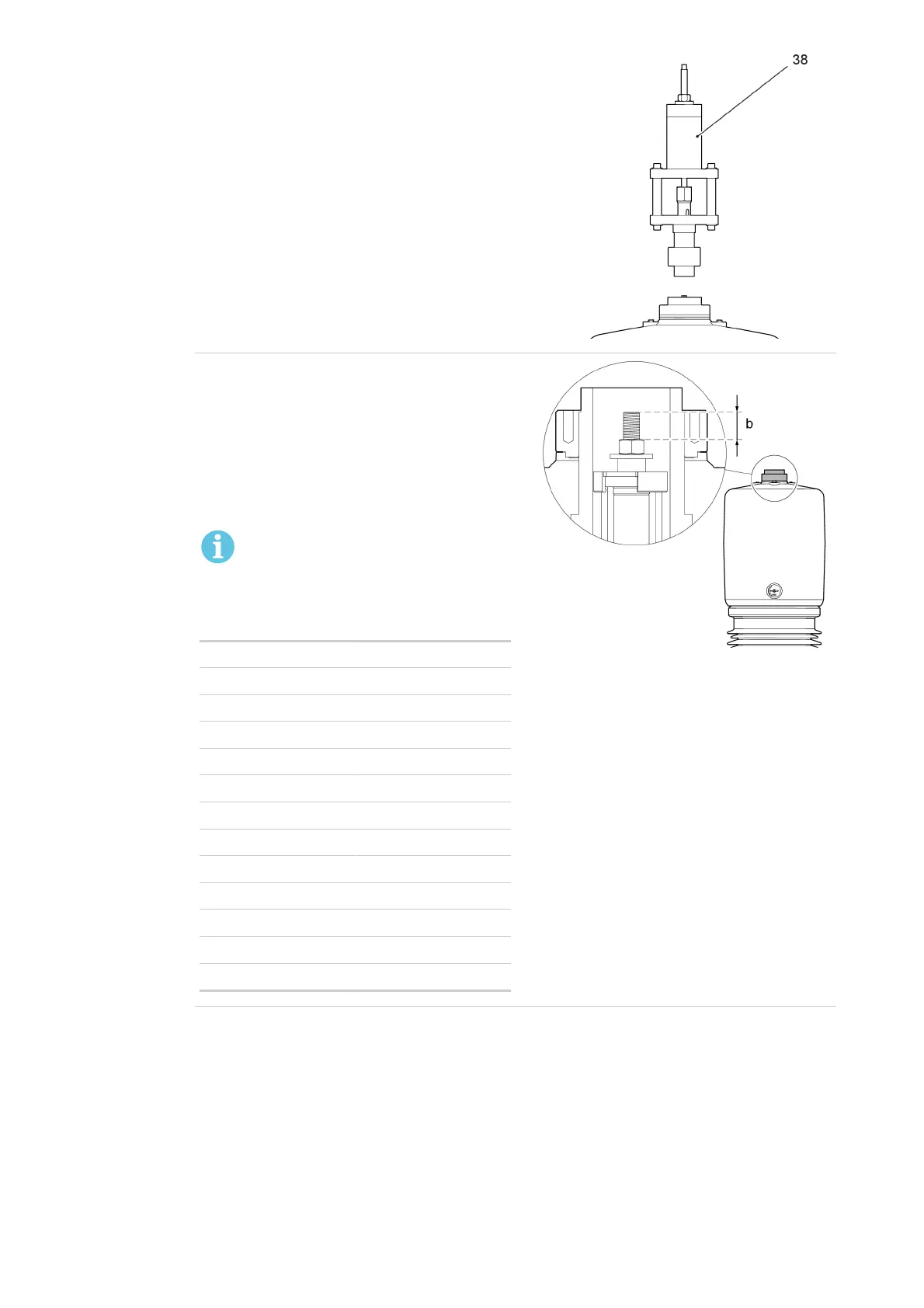
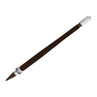
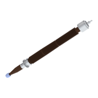
9. Remove the hydraulic jack (38) from the bushing.
G005068
10.
Make sure that the draw-rod extension is within
the tolerances:
1. Measure the distance (b).
2. Calculate the extension of the draw rod:
(b) minus (a).
3. Compare the calculated value (b-a) with the
dimension in the table.
NOTE!
Please contact ABB for special
bushings.
Type Extension
GOE 250 - 210 3.5 mm ±1.0
GOE 380 - 300 3.5 mm ±1.0
GOE 650 - 500 5.0 mm ±1.0
GOE 950 - 650 7.0 mm ±2.0
GOE 1050 - 750 9.0 mm ±2.0
GOE 1175 - 850 9.5 mm ±2.0
GOE 1300 - 1050 12.0 mm ±2.0
GOE 1425 - 1150 12.0 mm ±2.0
GOE 1550 - 1175 15.0 mm ±2.0
GOE 1675 - 1300 15.0 mm ±2.0
GOE 1800 - 1360 15.0 mm ±2.0
GOE 2550 - 1600 18.0 mm ±2.0
GOE 2550 - 1675 18.0 mm ±2.0
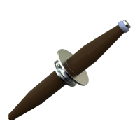
G005050