The load cell has the same sensitivity in both directions, so that the load cell can be installed in
the easiest manner.
Typical mounting arrangements are horizontal and inclined mounting.
2.5.1 Coordinate System
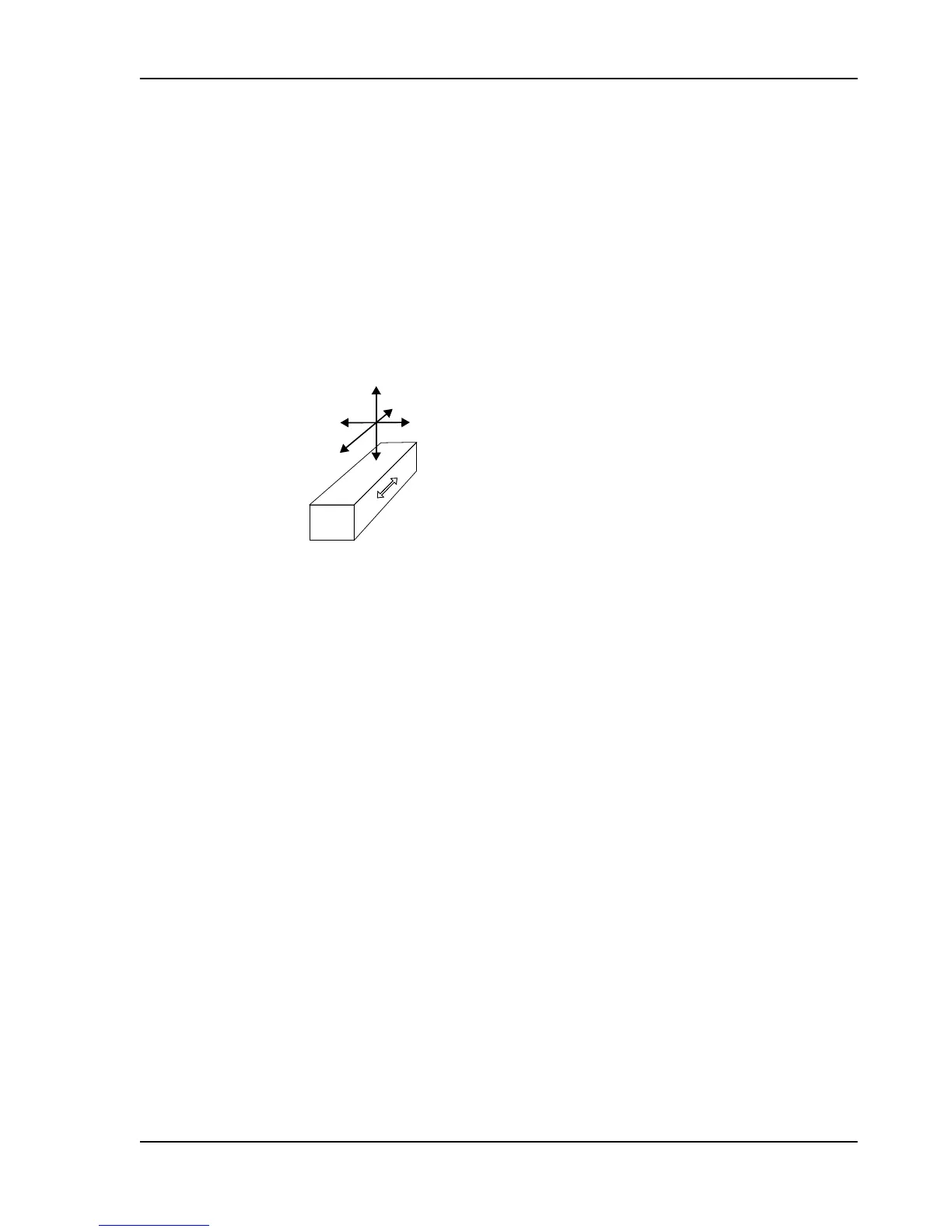
A coordinate system is dened for the load cell. This is used in force calculations to derive force
components in the load cell principal directions.
Where direction designations R, V and A are recognized as
sufxes for force components, F, this
represents the force component in the respective direction. The sufx R may be omitted, when
measuring direction is implied by the context.
Figure 10. Coordinate system dening directions used in force calculation
2.5.2 Horizontal Mounting
In the majority of cases horizontal mounting is the most obvious and easiest mounting method.
When calculating the force, the equations below must be used:
F
R
= T × (cos β - cos α)
F
RT
= 0
F
Rtot
= F
R
+ F
RT
= T × (cos β - cos α)
F
V
= T × (sin α + sin β)
F
VT
= Tare
F
Vtot
= F
V
+ F
VT
= T × (sin α + sin β) + Tare
where:
T = Web/strip tension
F
R
= Force component from web/strip tension in measurement direction, R
F
RT
= Force component from Tare in measurement direction, R
F
Rtot
= Total force in measurement direction, R
F
V
= Force component from web/strip tension in transverse direction, V
F
VT
= Force component from Tare in transverse direction, V
F
Vtot
= Total force in transverse direction, V
Tare = Force due to tare weight
Pressductor PillowBlock Load Cells, Horizontal Measuring PFTL 101, User Manual
2 Description
3BSE009965R0401 en Rev E 15