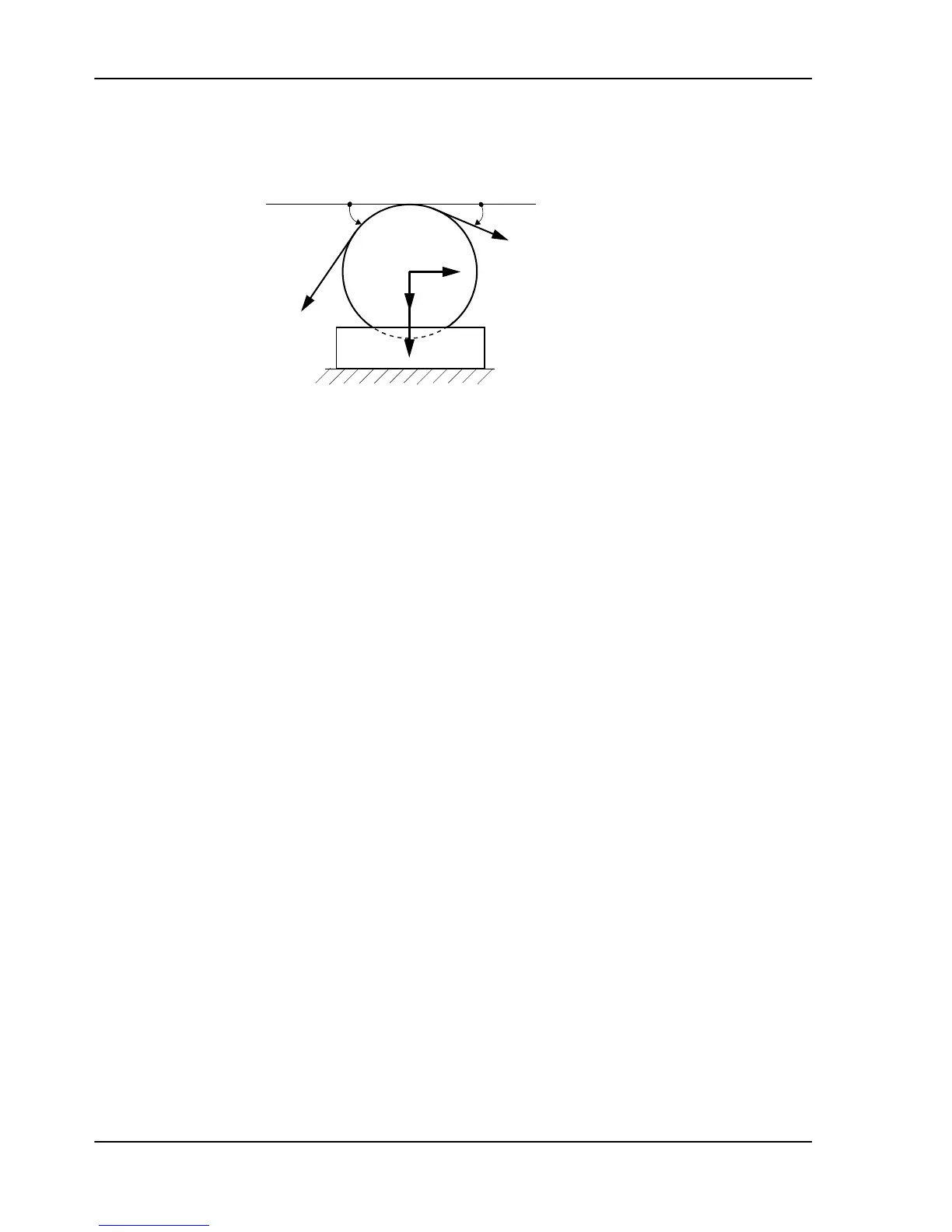
Figure 11. Horizontal Mounting
2.5.3 Inclined Mounting
Inclined mounting means arrangements in which the load cell is inclined relative to the horizontal
plane. In some cases this is the only option.
When calculating the force, the equations below must be used:
F
R
= T × [cos (β + γ) - cos (α - γ)]
F
RT
= Tare × sin γ
F
Rtot
= F
R
+ F
RT
= T × [cos (β + γ) - cos (α - γ)] + (- Tare x sin γ)
F
V
= T × [sin (α - γ) + sin (β + γ)]
F
VT
= - Tare × cos γ
F
Vtot
= F
V
+ F
VT
= T × [sin (α - γ) + sin (β + γ)] + Tare × cos γ
where:
T = Web/strip tension
F
R
= Force component from web/strip tension in measurement direction, R
F
RT
= Force component from Tare in measurement direction, R
F
Rtot
= Total force in measurement direction, R
F
V
= Force component from web/strip tension in transverse direction, V
F
VT
= Force component from Tare in transverse direction, V
F
Vtot
= Total force in transverse direction, V
Tare = Force due to tare weight
α =
Deection angle on one side of the roll relative the horizontal plane
β = Deection angle on the other side of the roll relative the horizontal plane
γ = Angle for load cell mounting surface relative the horizontal plane
Pressductor PillowBlock Load Cells, Horizontal Measuring PFTL 101, User Manual
2 Description
16 3BSE009965R0401 en Rev E