1.4 Function and Design
1.4.1 General
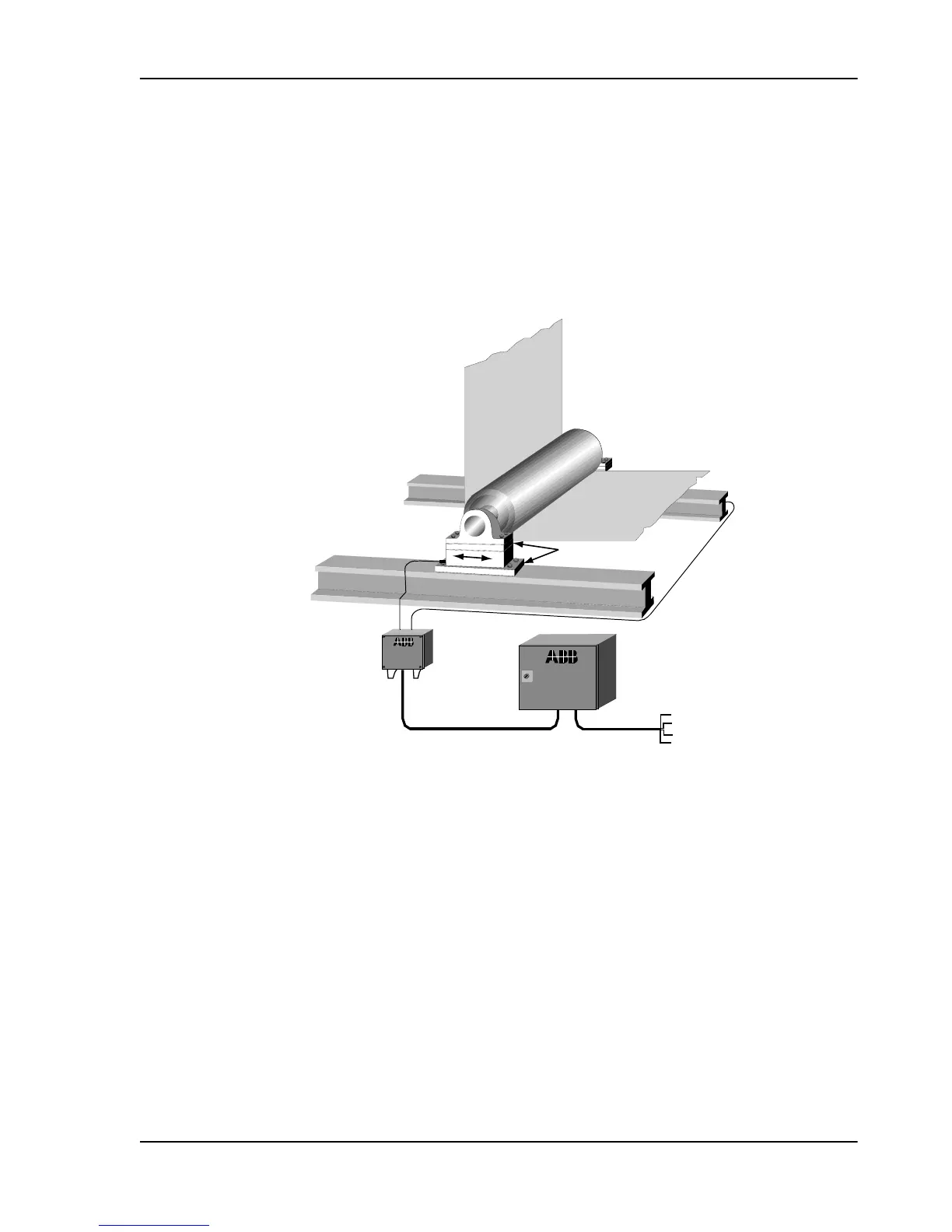
A complete measuring system normally consists of two load cells, a junction box, one control unit
with two measurement channels and cabling.
Figure 1. Complete Measuring System
1.4.2
Loads cells PFTL 101
The load cells are installed under the roll bearings, where they measure forces parallel to the
mounting surface.
The reactive force from the web/strip, which is proportional to the web/strip tension, is transferred
to the load cells via the roll and the bearings
The load cells are connected to the control unit via a junction box. The control unit converts the
load cell signals to DC voltages that are proportional to the reaction force. Depending on which
control unit is chosen, it is possible to have the analog signals for the two individual load cells (A
and B), the sum of the load cell signals (A+B), and/or the difference between the load cell signals
(A-B).
Pressductor PillowBlock Load Cells, Horizontal Measuring PFTL 101, User Manual
1 Introduction
3BSE009965R0401 en Rev E 7