When calculating it is important that the angles are set into the equations with the correct signs in
relation to the horizontal plane, see Figure 12. Inclined Mounting page 17.
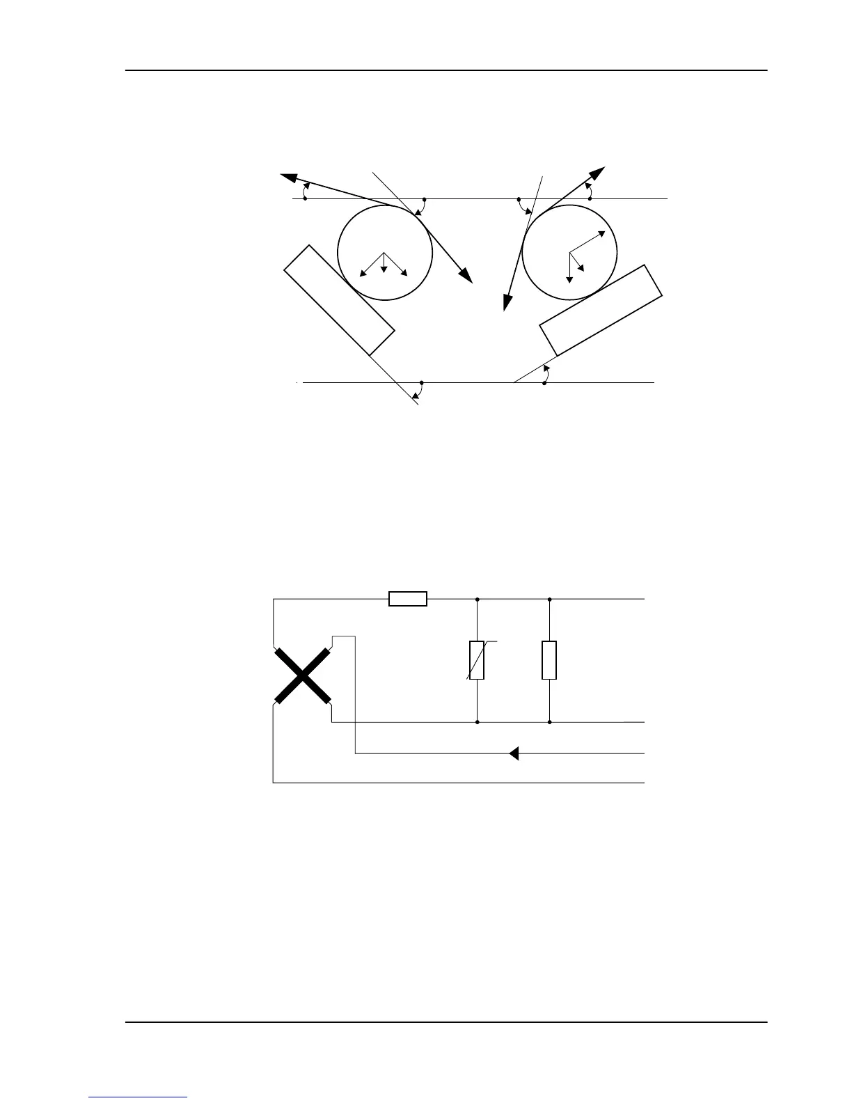
Figure 12. Inclined Mounting
2.6 The Electrical Circuit
The electrical circuit of the load cell is shown in the diagram below.
Figure 13. Load cell circuit diagram
The load cell is supplied with a 0.5 A, 330 Hz alternating current. The secondary signal is calibrated
for the correct sensitivity with a voltage divider R
1
- R
2
, and temperature compensation is provided
by thermistors T.
All resistances on the secondary side are relatively low. The output impedance is typically 1-3 Ω ,
which helps to suppress interference.
Pressductor PillowBlock Load Cells, Horizontal Measuring PFTL 101, User Manual
2 Description
3BSE009965R0401 en Rev E 17