27
FEM630 | ELECTROMAGNETIC FLOWMETER | OI/FEM630-EN REV. A
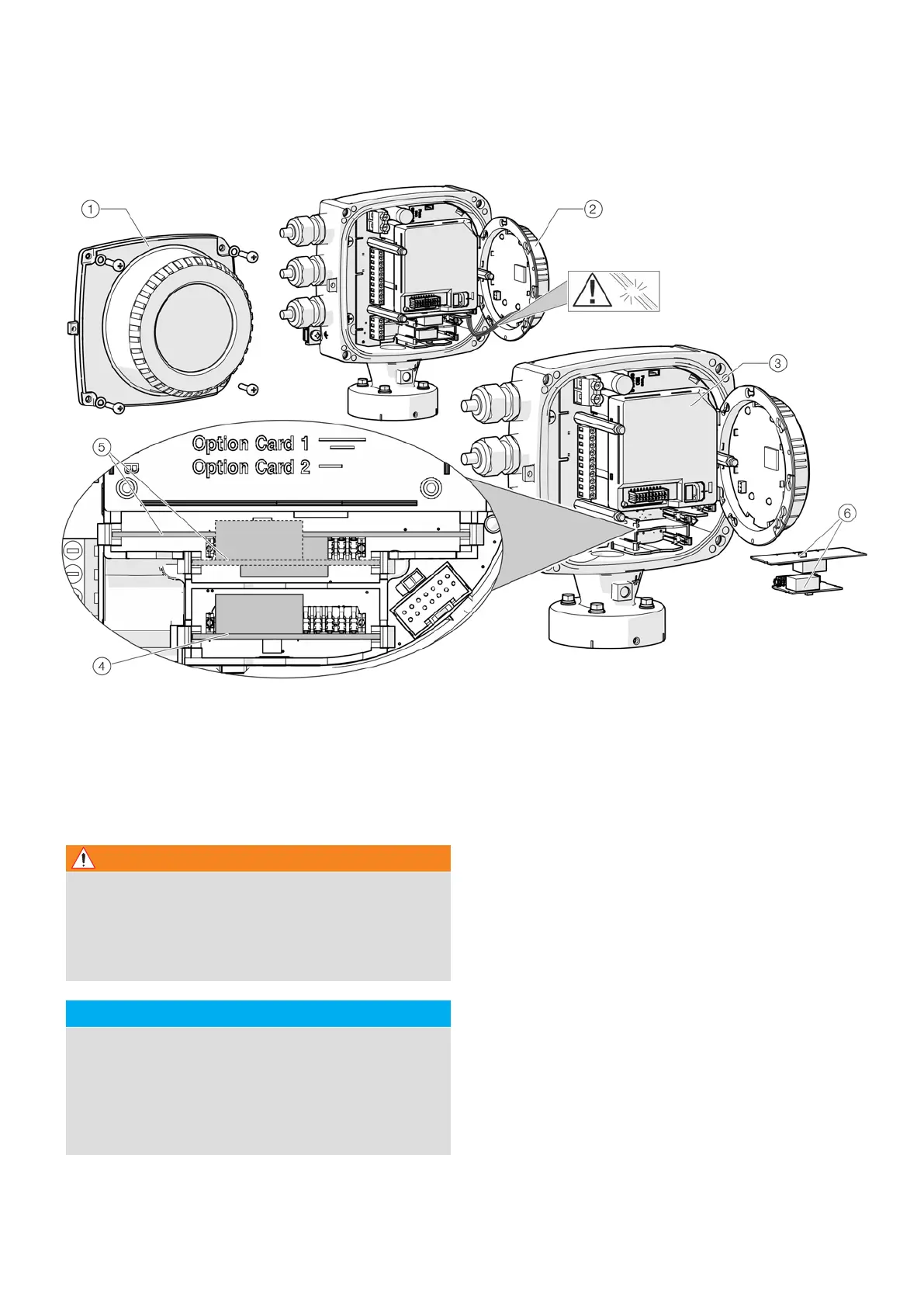
5 ...Installation
...Installing the plug-in cards
Cover
LCD indicator
Slot OC1
Slot OC2
Plug-in cards
1
2
3
4
5
Figure 27 Installation of plug-in cards (example, single-compartment housing)
1 Switch off the power supply.
2 Unscrew / remove the cover.
3 Remove the LCD indicator. Ensure that the cable harness
is not damaged.
Insert the LCD indicator into the bracket
4 (only for single-compartment housings)
5 Remove frontend board (only in integral mount design
and dual-compartment housing). Ensure that the cable
harness is not damaged.
6 Insert the plug-in card in the corresponding slot and
engage. Ensure that the contacts are aligned correctly.
7 Attach the frontend board, insert the LCD indicator and
screw on / replace the cover.
8 Connect outputs V1 / V2 and V3 / V4 in accordance with
Electrical connections on page 29.
9 After powering up the power supply, configure the plug-
in card functions.
Risk of injury due to live parts!
When the housing is open, contact protection is not
provided and EMC protection is limited.
• Before opening the housing, switch off the power
supply.
WARNING
NOTICE
Damage to components!
The electronic components of the printed circuit board
can be damaged by static electricity (observe ESD
guidelines).
• Make sure that the static electricity in your body is
discharged before touching electronic components.