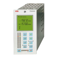
Do you have a question about the ABB Protronic 100 and is the answer not in the manual?
Essential safety guidelines to read and observe for correct device installation, operation, and maintenance.
Lists relevant DIN standards for bus system design, transmission media, and protocols.
Details the module's role in enhancing process engineering control via PROFIBUS-DP protocol for faster data exchange.
Enumerates the package contents of the PROFIBUS-DP slave module, including essential accessories.
Presents key technical data, environmental capabilities, and mechanical specifications for the module.
Guides the physical installation of the PROFIBUS-DP module into controller slots, recommending slot choices.
Explains the correct wiring and pin assignments for connecting the PROFIBUS-DP module to the bus system.
Provides a detailed breakdown of the signal assignments for each pin on the PROFIBUS-DP module's 7-pin connector.
Offers guidelines for wiring bus stations, including recommendations for stub line length and proper termination.
Describes the procedure for connecting the bus cable shield to the controller housing to ensure effective EMI/RFI shielding.
Covers the necessity and function of RS-485 repeaters for extending bus segments and managing signal amplification.
Explains how to configure the unique station address for each DP slave, noting limitations on automatic assignment.
Offers recommendations for reserving I/O data storage and managing parameter settings during commissioning.
Details the setup for parallel lateral communication via RS-232/RS-485 alongside PROFIBUS-DP.
Discusses running MODBUS and PROFIBUS-DP communications simultaneously, including access priority and data integrity.
Explains the unique ID number and role of the PROFIBUS-DP module in controller communication.
Describes how device database files define modules and data storage for modular slave configurations.
Highlights supported services like Freeze, Sync, Auto_Baud_Supp, and the non-supported AUTO_CLEAR function.
Defines cyclical operation, data block sizes, and the use of User_Prm_Data for configuring data transmission.
Details how to configure cyclic reading of specific values using ordered variable indices in User_Prm_Data.
Explains how to configure cyclic writing of values using negative variable indices in User_Prm_Data, emphasizing order.
Covers mixed cyclic read/write configurations using positive and negative indices in User_Prm_Data for efficient data exchange.
Clarifies the structure of the initial User_Prm_Data bytes and handling of unused variables for bus load optimization.
Describes acyclic data access using READ/WRITE services, leveraging slot and index for PROFIBUS-DP V1.
Outlines the request/response telegrams for the acyclic READ service, including parameter definitions and error handling.
Details the request/response telegrams for the acyclic WRITE service, covering parameters and error codes for data writing.
Explains acyclic data transfer methods using input/output data blocks as 'envelopes' for read/write operations.
Defines the structure and byte content of the request (output) and response (input) telegrams for the write service.
Specifies the request (output) and response (input) telegram structures and data for the read service, including status and error reporting.
Explains the structure of PROFIBUS configuration data, module grouping, and calculating data block sizes for reliable transmission.
Discusses how configuration tools derive data and the process for integrating new stations into the DP communication system.
Details the meaning of station status bits and diagnostic data bits, outlining required actions for troubleshooting.
Presents an overview of supported data types (REAL, INT, DINT, TIME, BOOL) and their respective value ranges and memory requirements.
Explains the method for calculating and using variable indices for accessing system and online variables across different data types.
Provides a table listing analog input variables with their decimal, hexadecimal read/write values, and data types.
Lists analog output variables with their decimal, hexadecimal read/write values, and data types.
Contains a table detailing digital input variables with their decimal, hexadecimal read/write values, and data types.
Lists digital output variables with their decimal, hexadecimal read/write values, and data types.
Covers parameters for loop display, automatic/cascade modes, and output variable feedback for Loop 1.
Details evaluation factors (K1-K16), PID control parameters, and scaling adjustments for Loop 1.
Explains parameters for setpoint control, manual/auto mode switching, and override selections for Loop 1.
Covers parameters for loop display, automatic/cascade modes, and output variable feedback for Loop 2.
Details evaluation factors (K1-K16), PID control parameters, and scaling adjustments for Loop 2.
Explains parameters for setpoint control, manual/auto mode switching, and override selections for Loop 2.
Covers parameters for loop display, automatic/cascade modes, and output variable feedback for Loop 3.
Details evaluation factors (K1-K16), PID control parameters, and scaling adjustments for Loop 3.
Explains parameters for setpoint control, manual/auto mode switching, and override selections for Loop 3.
Covers parameters for loop display, automatic/cascade modes, and output variable feedback for Loop 4.
Details evaluation factors (K1-K16), PID control parameters, and scaling adjustments for Loop 4.
Explains parameters for setpoint control, manual/auto mode switching, and override selections for Loop 4.
Lists variables indicating communication status, flags, and errors related to modules and I/O units.
Details free integer variables for communication, latent communication status, and module addresses.
Covers variables for program sequencing, timing, clock status, and setpoint generator functions.
Lists variables for output status correction, keyboard remote control, and table data.
Provides instructions for packaging the module for transport, including material selection and labeling.
Outlines specific requirements for overseas shipments, including desiccant use, foil sealing, and protective lining.
| Brand | ABB |
|---|---|
| Model | Protronic 100 |
| Category | Controller |
| Language | English |