14
EN
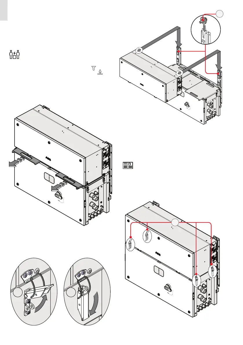
• Lift the power module (01) up to the bracket and over the
wiring box (02), using the handles (04) or another appropri-
ate lifting device.
Risk of injury due to the heavy weight of the
equipment.
• Insert the heads of two rear attachment pins (13) (placed on
the rear part of the power module) into the slots on the
bracket. For horizontal mounting, the two markings on
the bracket indicate the point where the edge of the power
module have to be placed to allow the engagement of the
rear attachment pins (13).
•
Remove the previously installed gasket protective covers
from the inverter by sliding it pulling from the handles.
Gasket protective covers and handles can be
reused for a new installation
• Fasten all of the four side latches (06) as shown in the pic-
tures.
PVS
PVS
A
B
(Continue to next page)
06
PVS
13
 Loading...


