136 Product manual - PVS-175-TL;A.1 Version
EN
• For each input channel the measurement must be performed between: positive to ground, negative to
ground, positive to negative.
Check sequence:
Positive to ground (PE)
Check sequence:
Negative to ground (PE)
Check sequence:
Positive to negative
First point Second point First point Second point First point Second point
CH1(+) PE CH1(-) PE CH1(+) CH1(-)
CH2(+) PE CH2(-) PE CH2(+) CH2(-)
CH3(+) PE CH3(-) PE CH3(+) CH3(-)
CH4(+) PE CH4(-) PE CH4(+) CH4(-)
CH5(+) PE CH5(-) PE CH5(+) CH5(-)
CH6(+) PE CH6(-) PE CH6(+) CH6(-)
CH7(+) PE CH7(-) PE CH7(+) CH7(-)
CH8(+) PE CH8(-) PE CH8(+) CH8(-)
CH9(+) PE CH9(-) PE CH9(+) CH9(-)
CH10(+) PE CH10(-) PE CH10(+) CH10(-)
CH11(+) PE CH11(-) PE CH11(+) CH11(-)
CH12(+) PE CH12(-) PE CH12(+) CH12(-)
12. Voltage absence test on AC side (wiring box)
•
Visually inspect the components to identify the presence of any overheating, signs of electric arcs,
failure of the insulating devices, loosen connections or cables not connected.
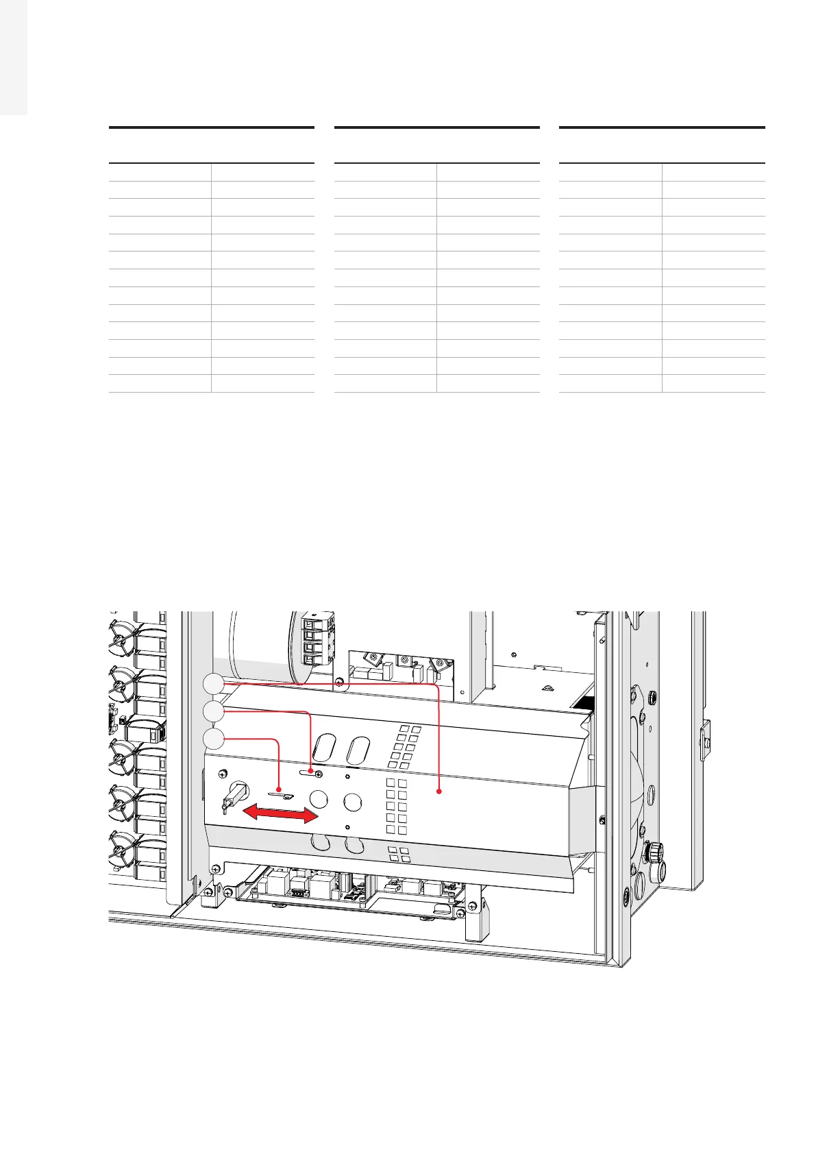
• Using a Philip screwdriver, unscrew the blocking screw (B) on the AC protective shield (23).
• Open the sliding cover (A) and block it in open position using the blocking screw (B). The opening of the
sliding cover will open the 6 holes that make accessible the VAT points on the AC connection busbar (27).
A
B
23
•
Perform VAT by inserting the voltage detector in the holes. With reference to below picture, the right
holes are designated for the insertion of the voltage detector (red arrows) while the left holes (in blue)
are designated as visually inspection holes, to make sure the electrodes of the voltage detector are
touching the main AC screws on the AC connection busbar (22).

 Loading...


