135Maintenance
EN
10. Discharge of the capacitor
Wait the internal capacitors to be discharged.
WARNING – B The discharge time of the stored energy is indicated on the regulatory label.
11. Voltage absence test on DC side (wiring box)
WARNING – B Before to approach the below operations all the steps from 1 to 9 included must
be successfully completed.
• Access to the wiring box (02) by opening the front wiring box cover (07).
•
Visually inspect the components to identify the presence of any overheating, signs of electric arcs,
failure of the insulating devices, loosen connections or cables not connected.
•
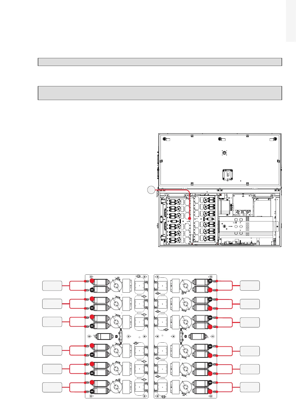
Test the absence of voltage on the DC inputs
using the voltage detector: the voltage
absence test on DC side must be carried out
on the DC surge arrester boards (21), shown
in the picture.
The layout of the DC surge arrester boards (21) is provided below, with reference of the points where
the input DC voltage absence test must be performed. The points are represented by the faston where
the cables (coming from DC switches (19)) are connected.
+
+
+
+
+
+
+
+
+
+
+
+
CH1
CH12
CH2
CH11
CH3
CH10
CH4
CH9
CH5
CH8
CH6
CH7
21

 Loading...


