138 Product manual - PVS-175-TL;A.1 Version
EN
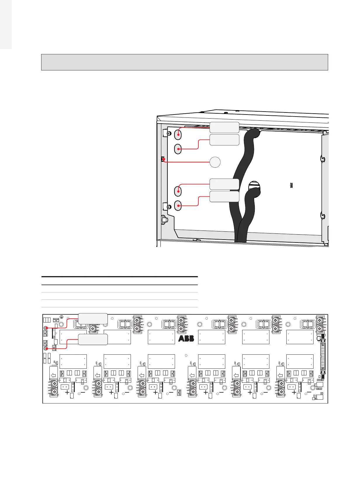
14. Voltage absence test on bulk capacitors (Power Module)
WARNING – B Before to approach the below operations all the steps from 1 to 12 included must
be successfully completed.
• Access to the power module box (01) by opening the power module front cover (06).
•
Visually inspect the components to identify the presence of any overheating, signs of electric arcs,
failure of the insulating devices, loosen connections or cables not connected.
•
Check the absence of voltage on the
DC input filter boards using the
voltage detector. The voltage absence
test on bulk capacitors must be
carried out on the DC input filter
boards, through the holes present in
the protective metal shield mounted
inside the power module, as shown in
the pictures. Holes are big enough to
visually inspect during the VAT
operations.
• The layout of the DC input filter board
is provided below, with reference of the points where the input DC voltage absence test must be
performed.
Check sequence First point Second point
Check #1 +BULK PE
Check #2 -BULK PE
Check #3 +BULK -BULK
R49 R51
R38
R39
R47 R48
R40
TP4
TP1
TP6
C26
R3
U15
R50
TP5
C20
R41
R9
U9
R1
R10
TP7
R4
C27
C21
R42
U10
R11
R12
R2
TP8
R5
C28
C22
R43
U11
R13
R14
R21
TP9
R6
C29
C23
R44
U12
R15
R16
R22
TP10
R7
C30
C24
R46
U13
R17
R18
R24
TP11
R8
C31
C25
R45
R19
U14
R20
R23
Q8
R55
C10
R53
C12
R32
C9
C8
R30
SH2
C7
U16
R31
R36
R35
R34
R33
U8
R26
R25
R29
C11
U7
TP3
TP2
D1
J2
R54
R37
R27
R28
TB15
TB16
U1
MP19
MP13
TB17
Q7
TB13
RT1
C13
TB1
C1
Q1
C43
C14
TB2
L1
C32
C44
MP20
MP14
U2
MP7
MP1
RT2
C33
TB3
C2
Q2
C47
C15
TB4
L2
C34
C48
MP21
MP15
U3
MP8
MP2
RT3
C35
TB5
C3
Q3
C45
C16
TB6
L3
C36
C46
TB14
MP9
MP3
MP22
MP16
U4
RT4
C37
TB7
C4
Q4
C49
C17
TB8
C38
L4
C50
MP23
MP17
U5
MP10
MP4
C5
RT5
C41
TB9
Q5
C53
C18
TB10
L5
C42
C54
U6
MP24
MP18
MP11
MP5
RT6
C39
C6
TB11
Q6
C51
C19
TB12
L6
C40
C52
MP12
MP6
J1
-BYP
-OUT
30
TO LOGIC BOARD
2
-BYP -OUT
+OUT
CH 5
-BYP -OUT
+OUT
CH 6
29
1
-BYP -OUT
+OUT
CH 3
RISO VCOM
-BYP -OUT
+OUT
CH 4
+BULK
+OUT
BULK
MID
CH 1
MID BULK
-BYP -OUT
+OUT
CH 2
-BYP
-OUT
30
TO LOGIC BOARD
2
29
1
-BYP -OUT
+OUT
CH 6
-BYP -OUT
+OUT
CH 5
+OUT
CH 4
-BYP -OUT
CH 3
RISO VCOM
ZGN.V3102.4
-BYP -OUT
+OUT
-BYP -OUT
+OUT
CH 2
BULK
+OUT
BULK
MID
CH 1
MID
-BULK
- BULK
+ BULK
PE
+ BULK
+ BULK
- BULK
- BULK

 Loading...


