148 Product manual - PVS-175-TL;A.1 Version
EN
8.8 Replacement of the COMM RS485 board
WARNING – B Some inverter parts may be subject to hazardous voltages for the operator. Before
performing any work on the inverter, refer to “Inverter total de-energization and safe access”
paragraph on this manual to know all the necessary step to safely operate on the inverter.
Replacing the RS485 line communication board is carried out on the wiring box (02) and may be necessary
in case of communication issues on RS485 line.
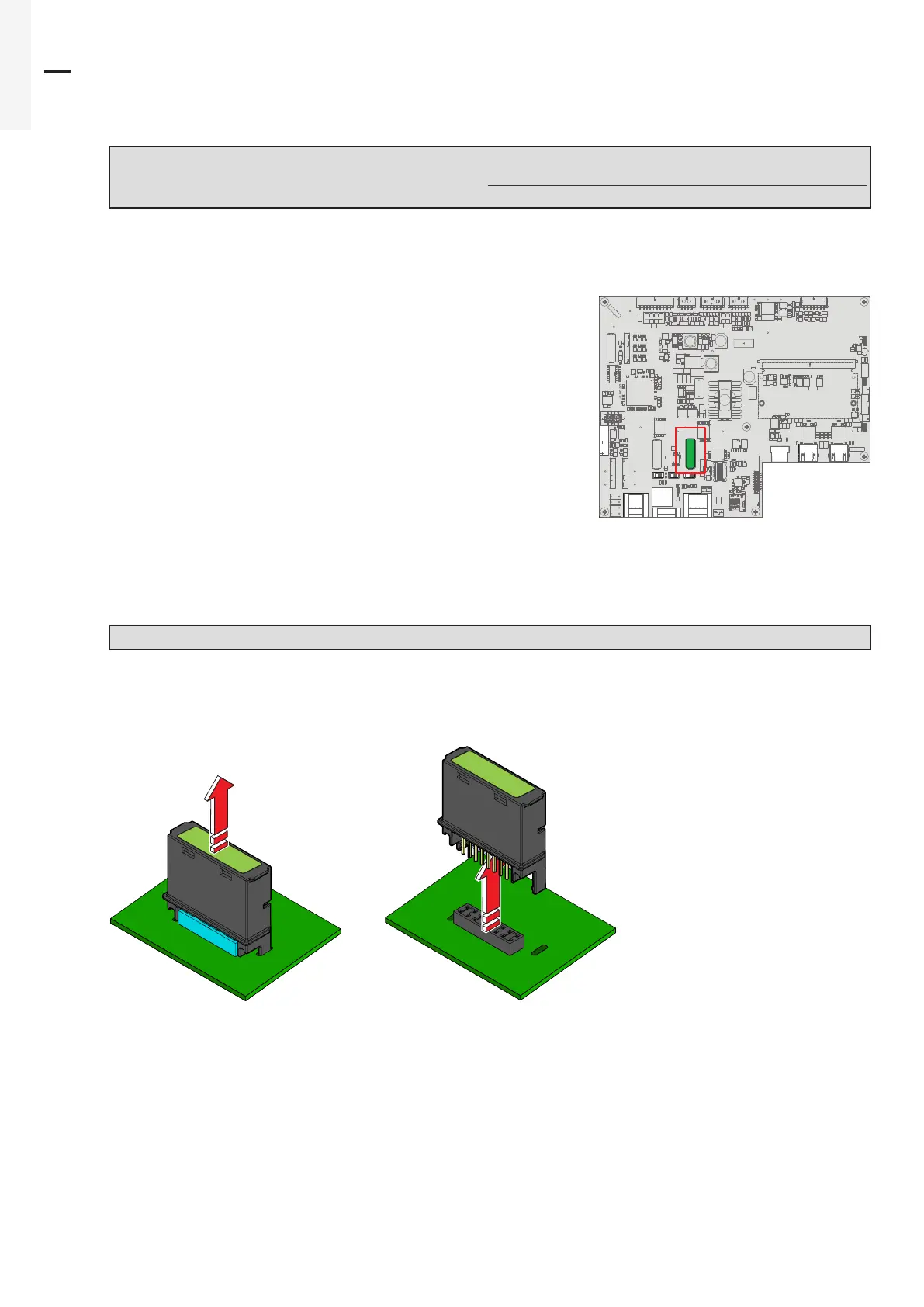
The RS485 line communication board is installed on the
communication and control board (26).
Procedure to replace the RS485 line communication board:
• Perform the “Inverter total de-energization and safe access” procedure before operate on the inverter.
• Open the front wiring box cover (07).
WARNING – B Do not open the power module cover (06) during the replacement operation.
• Remove the RS485 line communication board to be replaced.
• Install the new RS485 line communication board.
COMM RS485
COMM RS485
• Reconnect all the input strings and restart the inverter.
J9 J10
X2
J2
S2
J4
J1
S1 S3
J8
J3
J6
 Loading...


