68 Product manual - PVS-175-TL;A.1 Version
EN
5.6.4 Characteristics and sizing of the line cable
Depending of the type of the AC panel installed on the inverter, it’s possible to use single conductors
cables or a multipolar cable:
•
Single-core configuration have 3xM40 cable glands (11) for the “R”, “S”, “T” phases and a M32 cable gland
(12) for the grounding cable.
•
Multi-core configuration (optional) have a M63 cable gland (11) for the “R”, “S”, “T” phases and a M32
cable gland (12) for the grounding cable.
The cross-section of the AC line conductor cables must be sized in order to prevent unwanted disconnections
of the inverter from the grid due to high impedance of the line that connects the inverter to the power
supply; If the impedance is too high it causes an increase in the AC voltage which, on reaching the limit set
by the standards in the country of installation, causes the inverter to switch off.
The AC cables must be connected to the AC connection busbar (27) using a cable lug (not supplied) of a
suitable size for installation on the M10 threaded studs used for securing the cable.
Single conductor cable Multipolar cable
Cable diameter range
22 - 32 mm 37 - 53 mm
Min. conductor cross section
50 mm² 50 mm²
Cable lug dimensioning
b
a
for M10 Stud
a = 10.5 mm (min)
b = 40 mm (max)
for M10 Stud
a = 10.5 mm (min)
b = 40 mm (max)
ATTENTION – A The AC connection busbars (27) are in copper tin-plated; therefore if aluminum
cables are used, the correct coupling with the copper bars must be guaranteed by using
appropriate bi-metallic cable lug.
5.6.5 AC output cables connection
WARNING – B Before carrying out any operation, check that any external AC switch downstream
to the inverter (grid side) are in OFF position and check for voltage absence on the AC
conductors!
The AC cables must be passed into the inverter through the AC panel located on the right side of the wiring
box.
Depending of the version of the AC panel installed on the inverter it will be necessary to route the AC
output and ground cables into different ways:
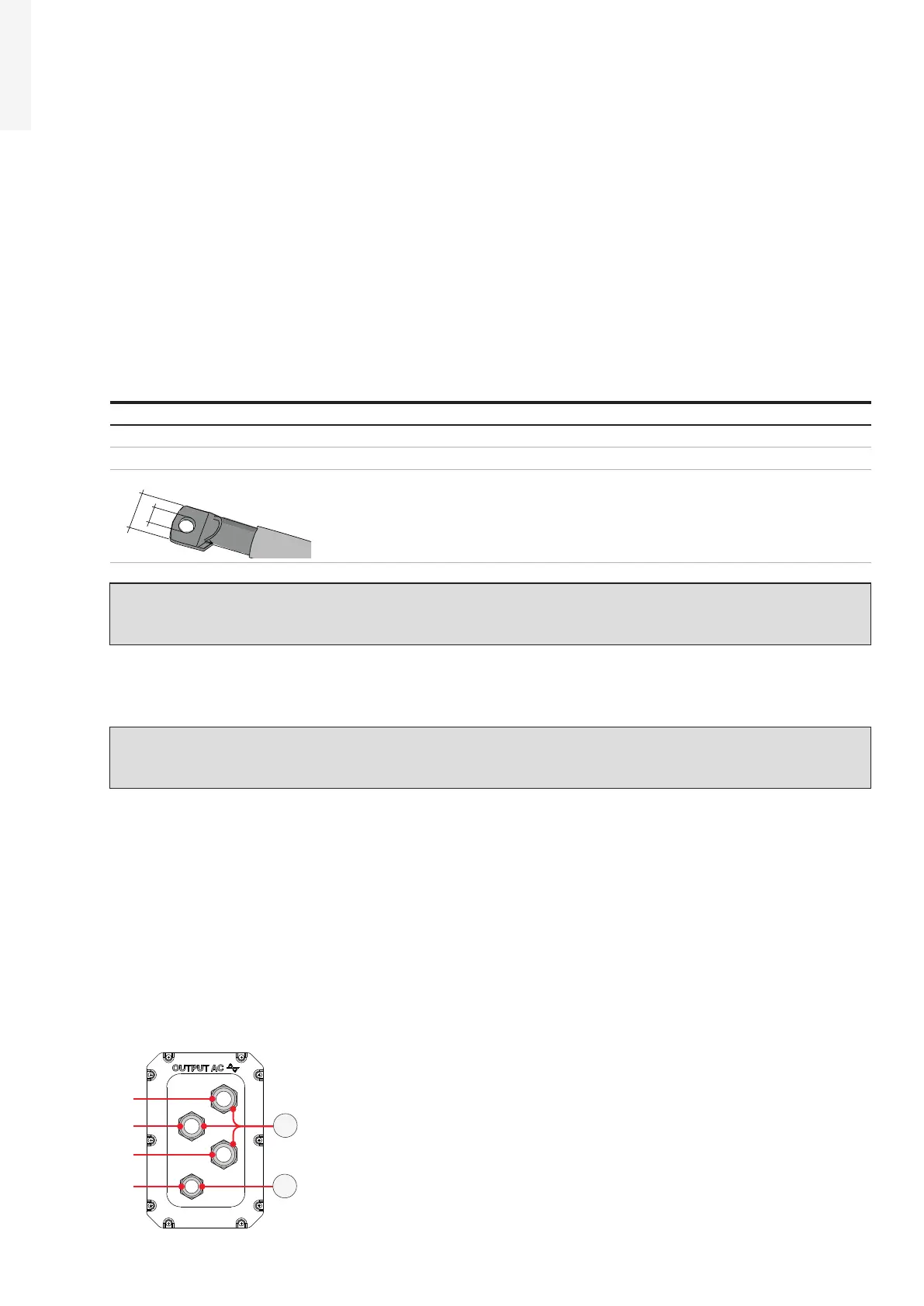
Single-core configuration (default):
3xM40 cable glands (11) for the “R”, “S”, “T” phases and a M32 cable gland (12) for the grounding cable.
In this configuration the AC output and ground cables must be inserted into the proper cable glands,
trying to follow a logical order based on the position of the internal connections:
R = Phase R (indicated with a label near the AC connection busbar (27))
S = Phase S (indicated with a label near the AC connection busbar (27))
T = Phase T (indicated with a label near the AC connection busbar (27))
12
11
PE
S
T
R