75Installation
EN
5.8.1 Installation procedure for quick-fit connectors
The model of connectors installed on your inverter must be matched by the same model of the respective
corresponding parts to be used (check the corresponding part on the manufacturer’s website or with
ABB).
WARNING – B To avoid damage to the equipment, when crimping cables to the connectors, pay
particular attention to polarity.
ATTENTION – A Using mating parts that are not compliant with the quick fit connector models
on the inverter could cause serious damage to the unit and lead to invalidation of the warranty.
NOTE – D Complete assembly instructions and specification of quick-fit connectors could be
found on manufacturer website.
Input cables must meet the connector requirements (cable diameter, conductor cross section) and
depends from connector models as shown in the table below:
Type Manufacturer Model P/N
Conductor cross
section
Ø cable gland
Male Stäubli PV-KBT4-EVO 2
32.0087P0001-UR
4 - 6 mm² 4.7 - 6.4 mm
32.0089P0001-UR
4 - 6 mm² 6.4 - 8.4 mm
32.0093P0001-UR
10mm² 6.4 - 8.4 mm
Female Stäubli PV-KST4-EVO 2
32.0086P0001-UR
4 - 6 mm² 4.7 - 6.4 mm
32.0088P0001-UR
4 - 6 mm² 6.4 - 8.4 mm
32.0092P0001-UR
10mm² 6.4 - 8.4 mm
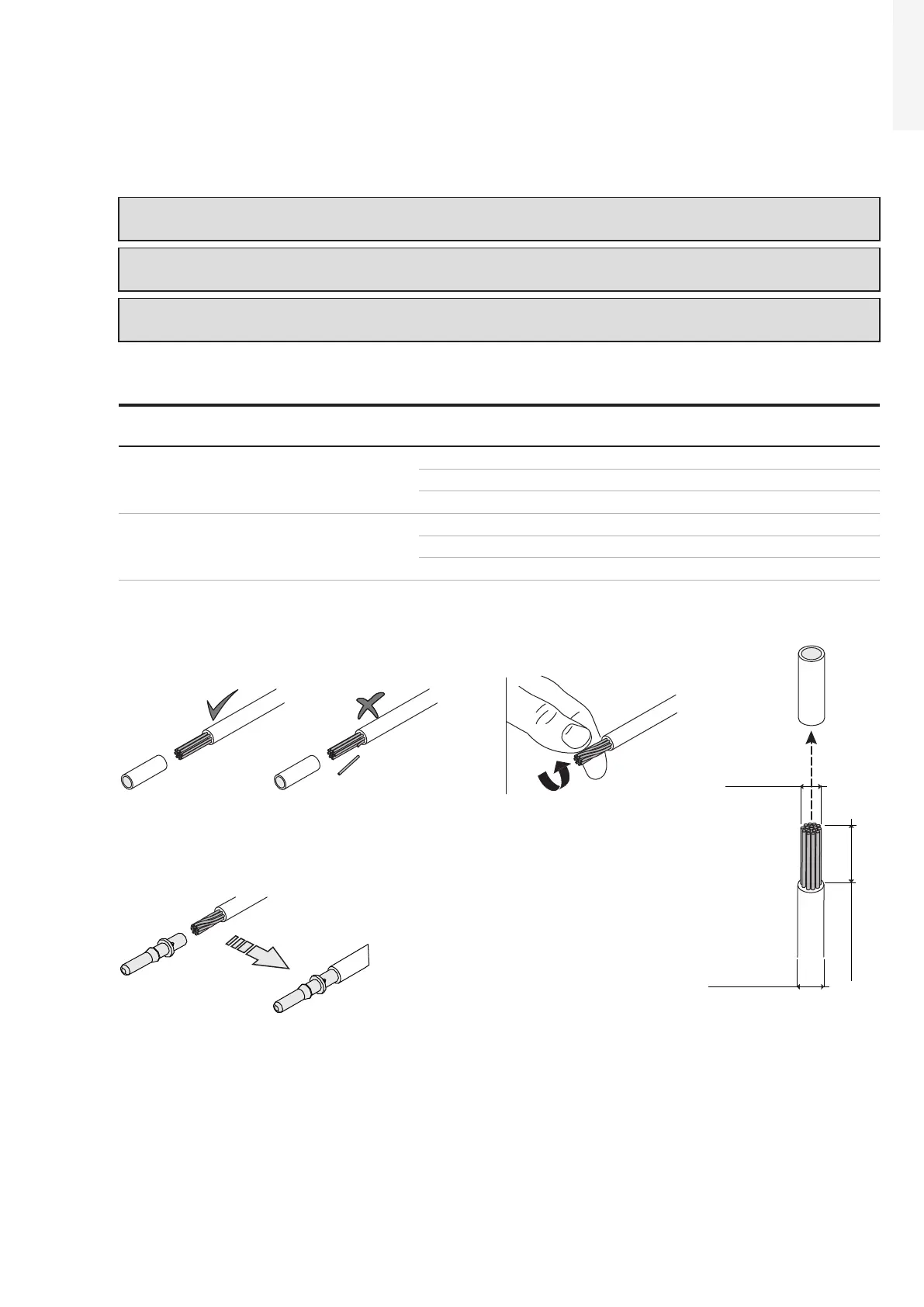
• Strip the cable over a lenght of 6,0 to 7,5mm using suitable equipment.
• Crimp the terminal to the conductor using the designated pliers.
6.0...7.5mm
*4...10mm
*4.7...8.4mm
(*): depends on connector models
2