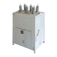
1. Use diagram on the previous page for references to troubleshooting the actuator control
board.
2. Disconnect source power to outdoor breaker.
3. Warning: removing cover exposes live voltage.
4. Remove the two #4 screws holding on the Push button plate and let it hang down.
5. Remove the four .250 X 20 screws from the corners of the control board cover.
Follow these instructions for a quick setup check on a breaker that has operated previously:
11.1 READY LIGHT IS OFF
1. Check pins 2 and 3 on KM1003 to confirm proper input voltage is applied.
2. Verify that there is 18 VDC on terminals 1 (-) to 3 (+) on KM1001.
3. Verify there is 80 VDC from KM1002 1 (-) to 3 (+).
4. If correct voltage is applied and DC is not reading, then the board needs to be replaced.

 Loading...