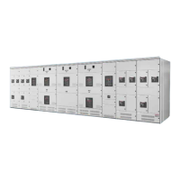
4.2 Housing
The doors of the breaker housing are removable and retained by hinge pins. The position
indicator is visible through the rear door. The breaker nameplate showing rating information,
serial number and shop order number is mounted on the side of the housing.
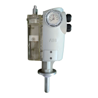
4.3 Magnetic Actuator
The magnetic actuator incorporates a very powerful permanent magnet assembly. When the
armature is in contact with the upper plate, the magnet produces a holding force in excess of
2700 lbs. The actuator connects to the crankshaft through a coupling connected to the upper
end of the actuator shaft. The manual trip is decoupled from the actuator shaft and is controlled
by its own stored spring energy being released against a dedicated lobe on the crankshaft.
The magnetic actuator has no user serviceable parts and therefore no lubrication or mainte-
nance is required. Should an actuator fail to operate, please immediately contact ABB for
service. The permanent magnets inside the actuator are extremely powerful, with the potential
to trap fingers.
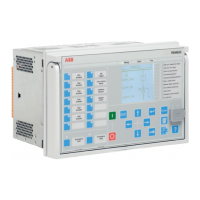
4.4 Actuator Controller
The actuator control board in the R-MAG breaker consists of a power supply, position indication,
switching assembly and capacitor charging system. Refer to Appendix A for an overview of the
actuator controller.
5. STANDARD PRODUCTION TESTS
Standard production tests include:
1. Verification of all wiring per connection diagrams.
2. Electrical Operation: Close and trip. Overcurrent response and automatic closing, with
relaying control option.
3. Functional check of all manual controls: Local/remote, non-reclosing, ground fault bypass,
etc.
4. Current Path Resistance Test: Three readings are made on each phase of the breaker using
a Biddle “Ductor”. Typical values do not exceed 150 micro ohms.
5. Voltage Withstand: The complete breaker is tested between live parts and tank, across open
contacts and between phases. In compliance with ANSI C37.09 and IEC, an AC dielectric
with-stand test at 80 kV is performed. Test duration is one minute.
6. Wiring Insulation: The terminal block connections are given an over-potential test of 1800
volts AC to ground (for 1 sec).

 Loading...