1MRK 500 124-UEN Section 3
HMI500
Operation Manual 47
Distributed busbar protection REB500
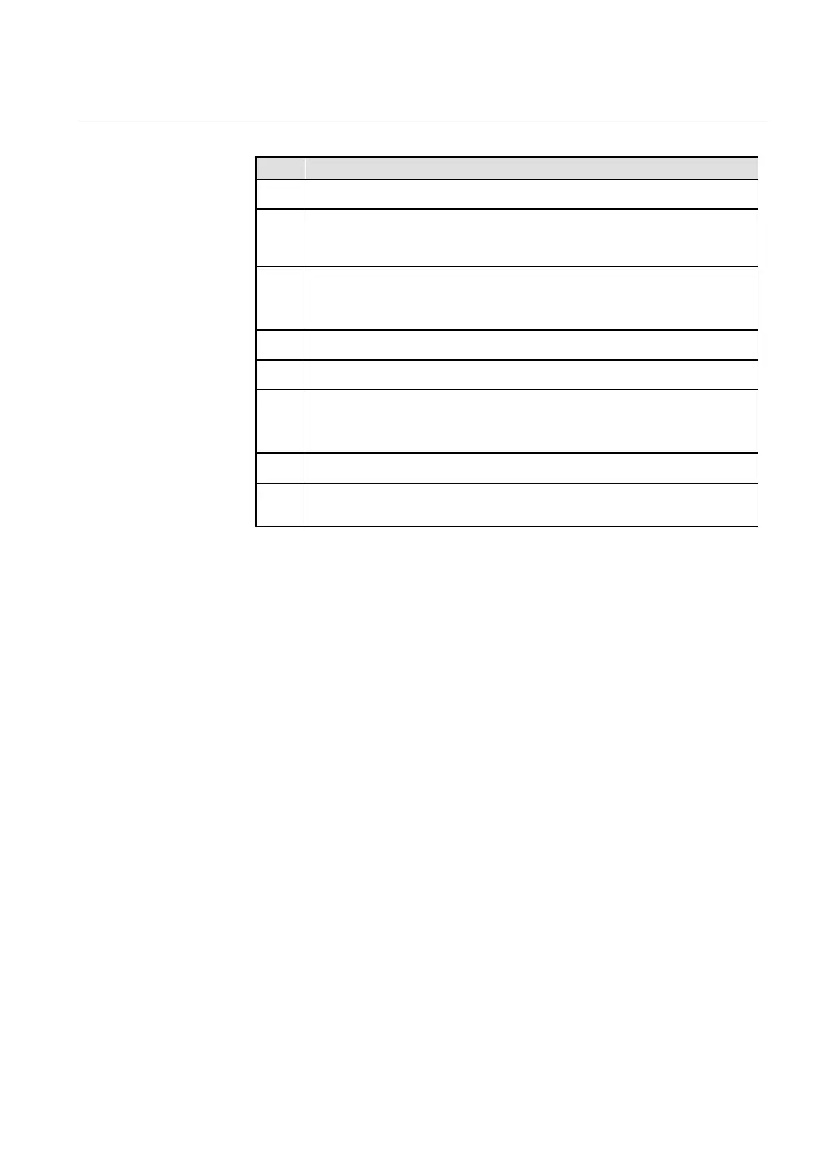
Table 9 Explanations of information flow using GOOSE as input
Step Description
1 Fault on line side
2 The line protection IED detects a fault, issues a trip command to the CB and indicates the
issued trip on the station bus by GOOSE. The GOOSE DA is received by the REB500
Central unit.
3 The REB500 central unit forwards the information to the bay unit (see Table 10).
Due to the REB500 configuration (made with the HMI500 tool) the GOOSE data attributes
of the issued trip is mapped to the breaker failure start signal(s).
4 The bay unit starts the breaker failure protection
5 The circuit breaker fails to trip (trip issued by line protection IED à see “Step 2”
6 If circuit breaker tripping is not successful after BFP timers have passed:
· a remote tripping command is sent (via teleprotection)
· intertripping is sent to the central unit
7 The Central unit performs the intertripping to the respective bay units
9 The bay units of the respective zone issue a trip command and consequently clear the
fault
3.6.4.1 Interface to System engineering Tool
Using GOOSE input signals for protection functions requires interaction between
the REB500 configurator (HMI500) and the System engineering tool. Table 10
provides an overall view of the engineering process.