UL1
UL2
UL3
UN
UL1
UL1
UL2
UL3
I
E
D
T
E
S
T
S
E
T
I
E
D
IEC07000108-1-en.vsd
UL2
UL3
UN
1
2
IEC07000108 V2 EN
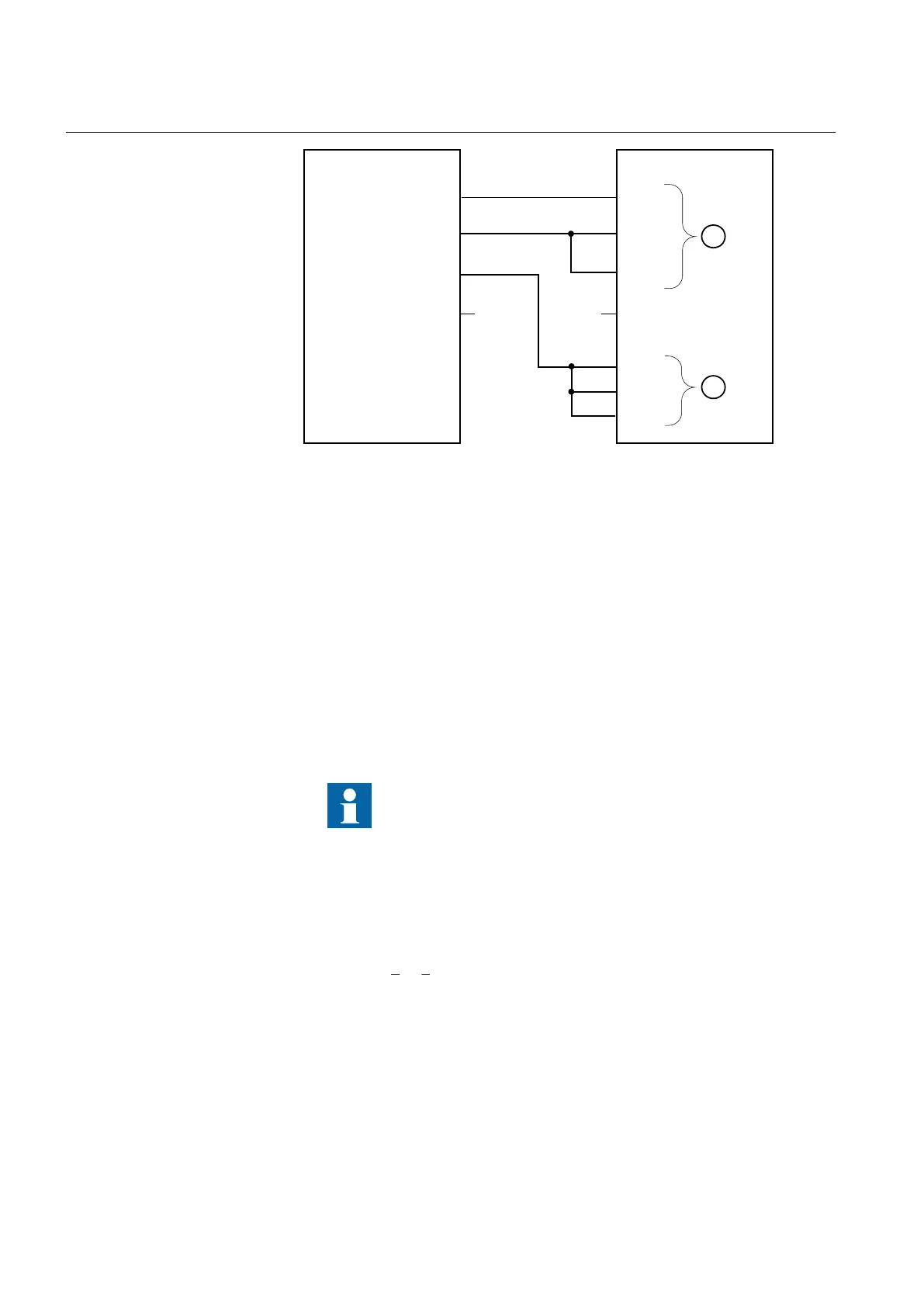
Figure 20: Connection of the test set to the IED for test of alarm levels, trip
levels and trip timer
where:
1 is three-phase voltage group1 (U1)
2 is three-phase voltage group2 (U2)
2. Apply 1.2 · Ur (rated voltage) to the U1 and U2 inputs.
3. Decrease slowly the voltage of in phase UL1 of the test set until the ALARM
signal is activated.
The ALARM signal is delayed with timer tAlarm
4. Check the alarm operation level by comparing the differential voltage level at
ALARM with the set alarm level UDAlarm.
5. Continue to slowly decrease the voltage until START signal is activated.
6. Check the differential voltage operation level by comparing the differential
voltage level at START with the set trip level UDTrip.
7. Repeat steps
1 to 6 to check the other phases.
Observe that the connections to U1 must be shifted to test another phase. (UL1
to UL2, UL2 to UL3, UL3 to UL1)
10.5.4.3 Check of trip and trip reset timers
Procdure
Section 10 1MRK 511 360-UEN A
Testing functionality by secondary injection
124 Bay control REC670 2.1 IEC
Commissioning manual

 Loading...


