IEC09000021-2-en.vsd
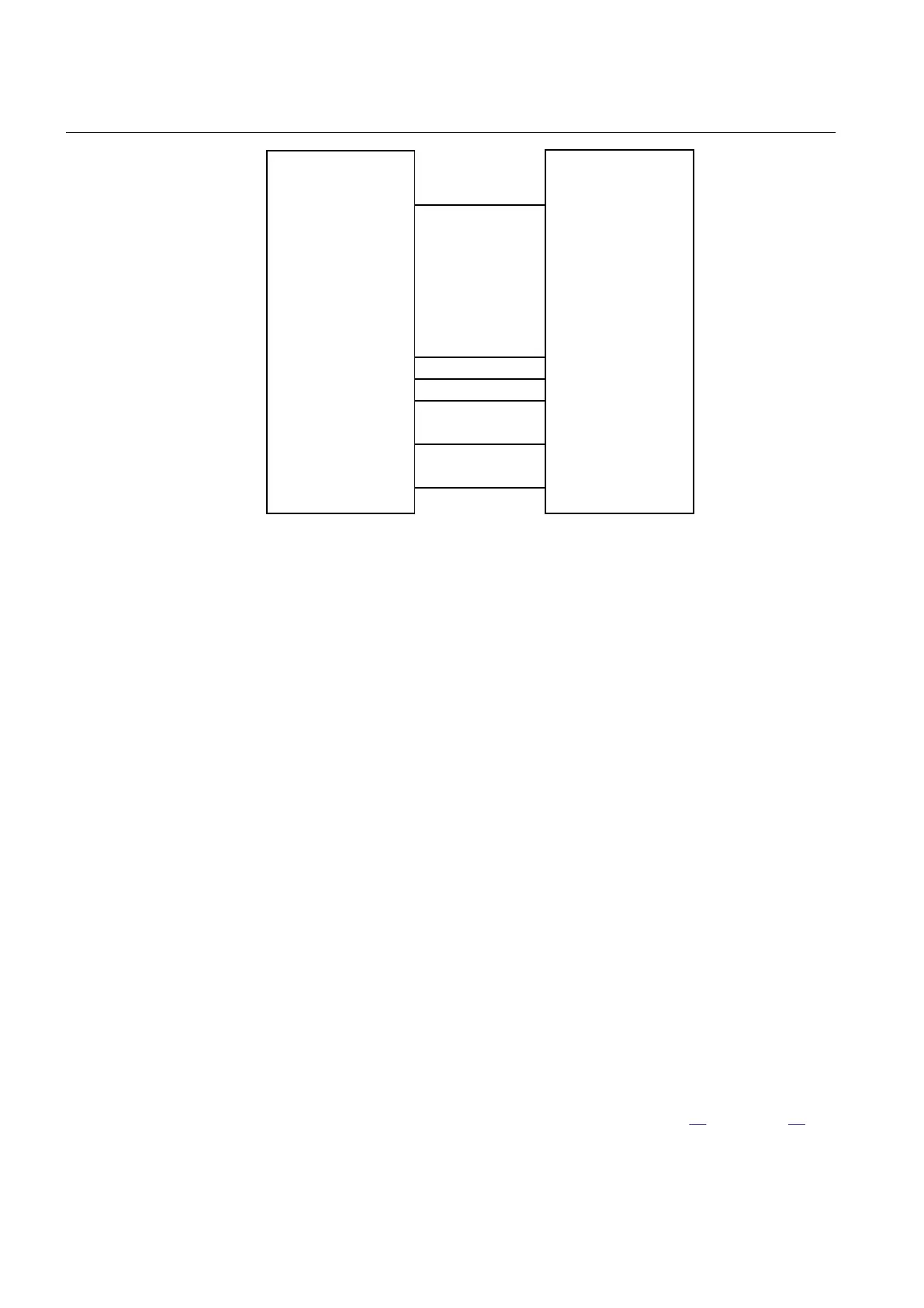
IED test set
NI
IED
NI
L1U
L2U
L3U
NU
U1
U2
U3
NU
TRIP
IEC09000021 V2 EN
Figure 14: Principle connection of the test set
Values of the logical signals belonging to the sensitive directional residual
overcurrent and power protection are available on the local HMI under Main menu/
Test/Function status/Current protection/SensDirResOvCurr(67N,IN>)/
SDEPSDE(67N,IN>):x
10.4.6.1 Measuring the operate and time limit for set values
Operation mode 3I
0
· cosφ
Procedure
1. Set the polarizing voltage to 1.2 · UNRel> and set the phase angle between
voltage and current to the set characteristic angle (RCADir). Note that the the
current lagging the voltage.
Take setting RCAComp into consideration if not equal to 0.
2. Inject current until the function picks up, and make sure that the operate current
of the set directional element is equal to the INcosPhi> setting.
The I Dir (3I
0
· cosφ) function activates the START and STDIRIN output.
3. Assume that φ´ is the phase angle between injected voltage (3U
0
) and current
(3I
0
) i.e. φ´ = RCADir-φ. Change φ´ to for example 45 degrees. Increase the
injected current until the function operates.
4. Compare the result with the set value and make sure that the new injected 3I
0
·
cos φ is equal to the setting INcosPhi>..
Take the set characteristic into consideration, see Figure
15 and Figure 16.
Section 10 1MRK 511 360-UEN A
Testing functionality by secondary injection
92 Bay control REC670 2.1 IEC
Commissioning manual

 Loading...


