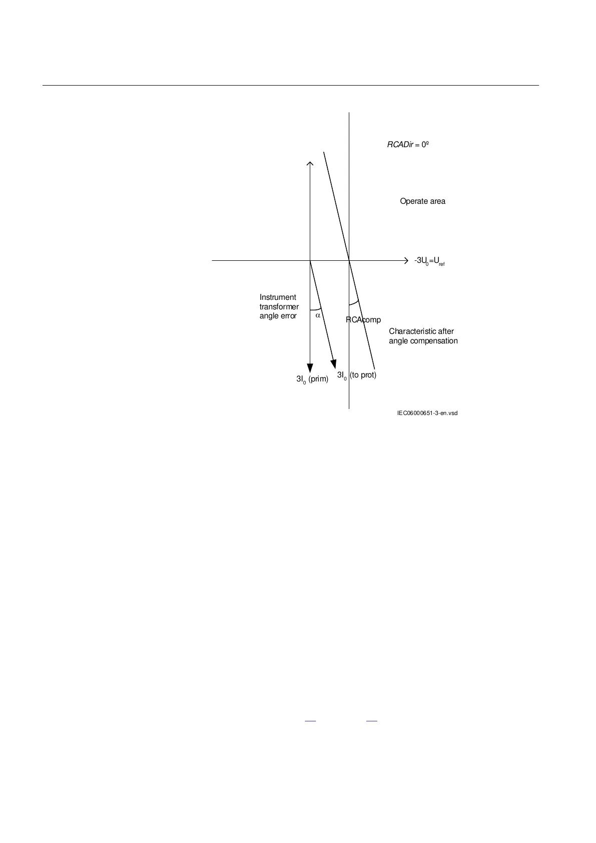
-3U
0
=U
ref
Operate area
Instrument
transformer
angle error
3I
0
(prim)
3I
0
(to prot)
Characteristic after
angle compensation
RCAcomp
IEC06000651-3-en.vsd
RCADir = 0º
IEC06000651 V3 EN
Figure 16: Explanation of RCAcomp
Operation mode 3I
0
· 3U
0
· cos φ
1. Set the polarizing voltage to 1.2 · UNRel> and set the phase angle between
voltage and current to the set characteristic angle (RCADir). Note that the current
lagging the voltage.
2. Inject current until the function picks up, and make sure that the operate power
is equal to the SN> setting for the set directional element.
Note that for operation, both the injected current and voltage must be greater
than the set values INRel> and UNRel> respectively.
The function activates the START and STDIRIN outputs.
3. Assume that φ´ is the phase angle between injected voltage (3U
0
) and current
(3I
0
) i.e. φ´ = RCADir-φ. Change φ´ to for example 45 degrees. Increase the
injected current until the function operates.
4. Compare the result with the set value and make sure that the new injected 3I
0
·
3U
0
· cos φ is equal to the setting SN>. Take the set characteristic into
consideration, see figure
15 and figure 16.
Section 10 1MRK 511 360-UEN A
Testing functionality by secondary injection
94 Bay control REC670 2.1 IEC
Commissioning manual

 Loading...


