REF 542plus switchbay protection and control unit
Manual Part 3: Installation and Commissioning
1VTA100004-en DMS,2001-10-04 REF542plus: Installation and Commissioning 19 / 80
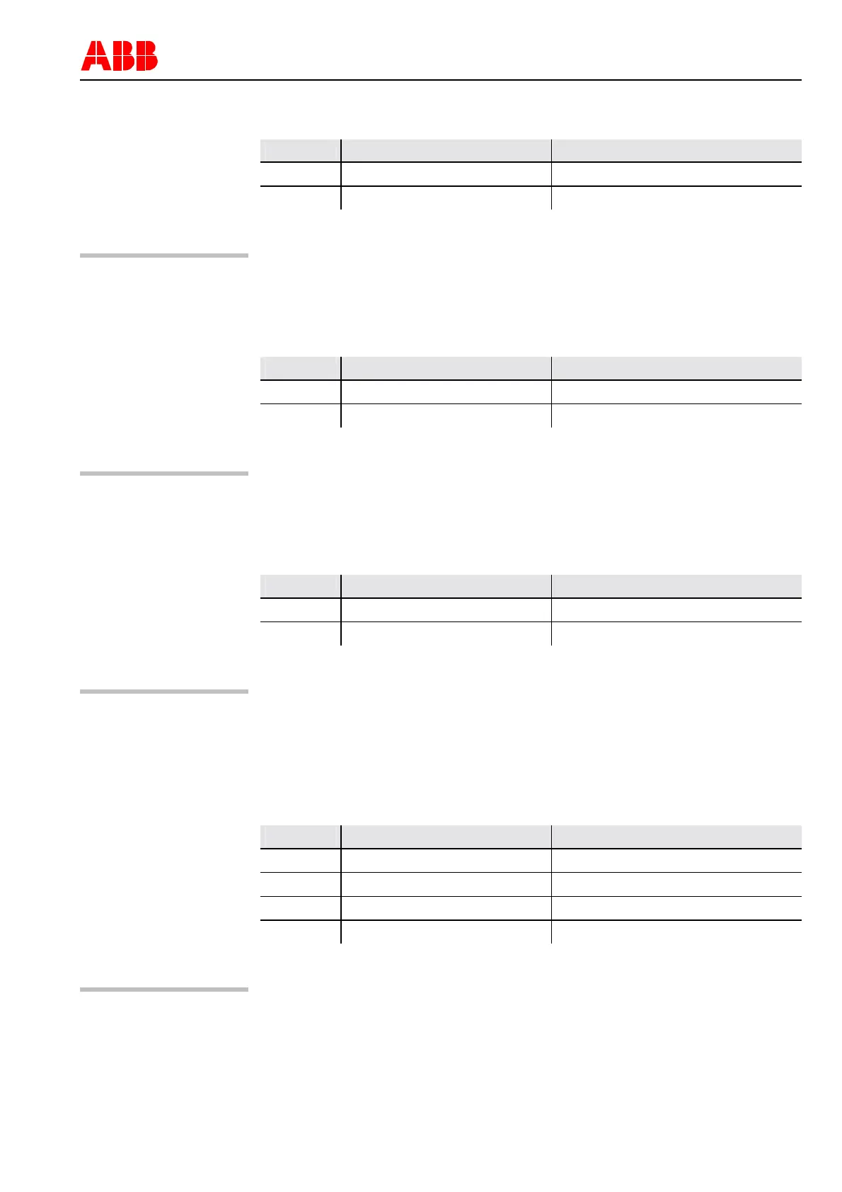
Table 5: Connectors on Central Unit for SPABUS connection, glass fiber optical cable
Connector Descriptions Type of connector plug
X60 TX (optical interface) ST plug HITRONIC ST-125
X61 RX (optical interface) ST plug HITRONIC ST-125
Caution
The cable length for SPABUS connection with glass fiber optical cable should
not exceed 1000 m
Table 6: Connectors on Central Unit for LON per LAG 1.4 respectively IEC 60870-5-103
Connector Descriptions Type of connector plug
X60 TX (optical interface) ST plug HITRONIC ST-125
X61 RX (optical interface) ST plug HITRONIC ST-125
Caution
The cable length for LON (per LAG 1.4) connection with glass fiber optical ca-
ble should not exceed 2000 m
Table 7: Connectors on Central Unit for MODBUS RTU, electrical RS485
Connector Descriptions Type of connector plug
X60 RS485 channel 1 2pin Weidmueller BLAT2BSNOR
X61 RS485 channel 2 2pin Weidmueller BLAT2BSNOR
Caution
To connect to the upper level automation system with MODBUS RTU a twisted
pair cable shall be used. If the cable is shielded, connect only one side of the
shield to the earth screw of the housing. The maximum baud rate is 115000
bit/s. The cable length should not exceed 130 m
Table 8: Connectors on Central Unit for MODBUS, glass fiber optical cable
Connector Descriptions Type of connector plug
X62 RX channel 1 (optical interface) ST plug HP type HFBR *XS*
X63 TX channel 1 (optical interface) ST plug HP type HFBR *XS*
X64 RX channel 2 (optical interface) ST plug HP type HFBR *XS*
X65 TX channel 2 (optical interface) ST plug HP type HFBR *XS*
Caution
The maximum baud rate is 115000 bit/s with glass fiber optical cable. Its length
should not exceed 2000 m