76
Preparing for test Chapter 11
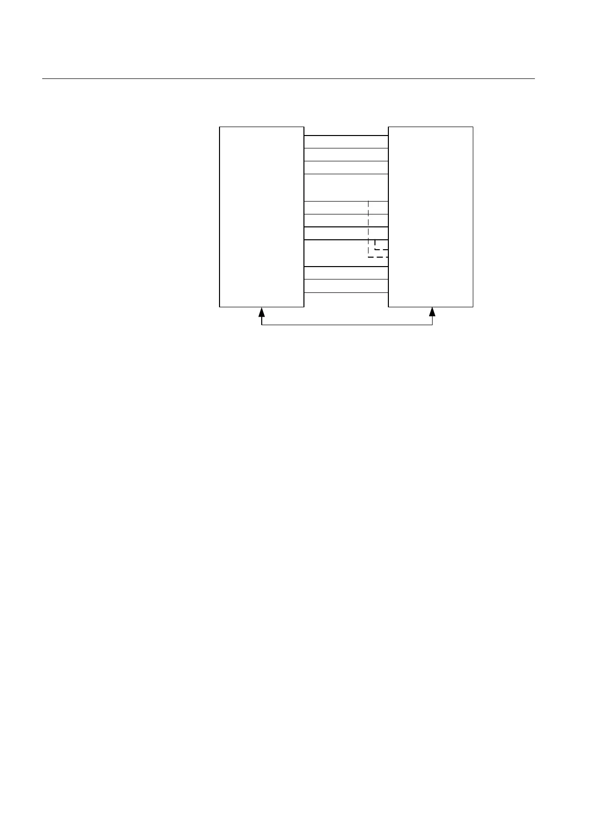
Verifying settings by secondary
injection
Figure 25: Connection of the test set to the REx670 IED
2.5 Verifying the connections and the analog inputs
The user must verify that the connections are correct and that the analog signals are measured
correctly.
Procedure
1. Inject a symmetrical three-phase current and voltage at rated value.
2. Inject a through going phase-to-phase current and voltage at rated
value. (This is for RET only)
3. Compare the injected value with the measured value.
The voltage phasor and current phasor menus are located under the Mea-
surements folder in the LHMI:
Measurements\Monitoring\Analog primary values
and
Measurements\Monitoring\Analog secondary values
Take into consideration ratio factor settings for CT’s and VT’s.
IL1
IL2
IL3
NI
UL1
UL2
UL3
UN
IL1
IL2
IL3
UL1
IN (I4,I5)
TRIP L1
TRIP L2
TRIP L3
IED TEST SET
REx 670
en05000467.vsd
UL2
UL3
UN
UN (U4,U5)
IEC61850