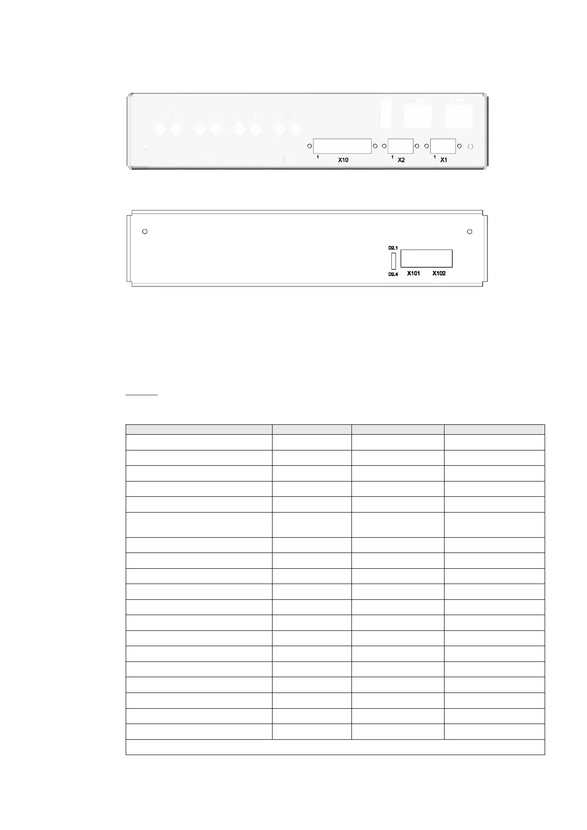
Side plate connector positions
0 0 0 0 0 0 0 0
00 00 00 00
0
IEC18000526 V1 EN-US
Figure 16: SAM600-CT module electrical Ethernet side view
IEC18000527 V1 EN-US
Figure 17: SAM600-CT module fiber optical Ethernet side view
Wiring diagrams
Wiring diagrams for SAM600-CT can be found in document 1KHL511912.
Connector descriptions
Table 9 lists the interface descriptions for the SAM600-CT module.
Table 9: Interfaces for SAM600-CT
Interface Connector Pin Remark
Power supply interface X1/X2
Power supply - VDC X1 1
Power supply +24 VDC (main power) X1 2
Power supply - VDC X1 3
Power supply - VDC X2 1
Power supply +24 VDC (redundant
power)
X2 2
Power supply - VDC X2 3
Digital interface X10
Test switch indication X10 1
Not used X10 2
Not used X10 3
Not used X10 4
Binary input of common GND X10 5
Shielding GND X10 6
Shielding GND X10 7
Analog interface X11-X14
Current phase L1- X14 1
Current phase L1+ X14 2
Current phase L2- X13 1
Table continues on next page
1MRK 511 434-UEN B Section 7
Technical Data
SAM600 Process Bus I/O System 41
Operation Manual
© Copyright 2017 ABB. All rights reserved