5 Electrical Interconnections Converter
16 S4 D184B122U02
5.5.3 Flowmeter Primary DN 1 to DN 1000 [1/25” - 40”],
Converter Field Mount Housing with PROFIBUS PA
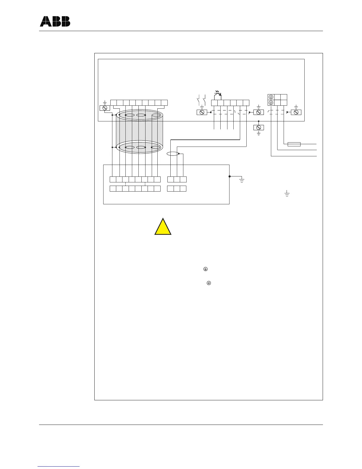
Fig. 7: Interconnection Diagram Converter S4 with PROFIBUS PA
2-
L
M3
M198
97
41
N
1+
1)2)3)4)
1
2S
2
16
1S
3
42
5)
2S
3
1S
16
3
SE
M3
M1
SE
3
12
U-U+
16
33
SE
M3
M1
SE
12
6)
U+
U-
6)
3a)
Earth
Earth
Converter S4
Wall Mount Housing
Flowmeter Primary
With preamplifier
(always for DN1–DN8
[1/25”-5/16”])
Comment:
We recommend that shielded output cables be used with the shields connected to earth at one end.
!
Attention!
If the flowmeter primary includes a preamplifier for low conductivity of for small flow-
meter size DN 1 to DN 8 [1/25” to 5/16”], then the voltage supply ±12 V DC must be
connected to the terminals U+ and U- and be connected to the flowmeter primary as
well as at the converter.
1) Supply Power
High voltage:
Low voltage:
Frequency:
AC 85–253V
Terminals L, N,
AC 20.4 to 26.4 V
DC 20.4 to 31.2 V
Terminals 1+, 2-,
47 Hz ≤ f ≤ 53 Hz; 50 Hz supply power
56 Hz ≤ f ≤ 64 Hz, 60 Hz supply power
2) Magnet Coil Supply: Shielded 2 x 1 mm² CE Typ 227 TEC 74
ABB Part No. D173D147U01
10 m included in shipment Standard
3) PROFIBUS PA: PROFIBUS PA per IEC 61158-2 (Profile 3.0)
U = 9–32 V, I = 10 mA (normal operation)
I = 13 mA (during error condition/FDE)
3a) Bus Termination: Bus termination using installed bus termination components, close hook switches
For interconnection example using M12 plug see Page 19
4) Contact Output:
Function:
Software selectable
Passive
„closed“: 0V ≤ U
CEL
≤ 2 V, 2 mA ≤ I
CEL
≤ 220 mA
„open“: 16 V ≤ U
CEH
≤ 30 V, 0 mA ≤ I
CEH
≤ 2 mA
Terminals: 41, 42
5) Shielded Signal Cable: ABB Part No. D173D018U02, 10 m included in shipment.
6) Shielded Signal Cable: Voltage supply for flowmeter primary with preamplifier
Terminals +U, -U instead of 2S and 1S in the standard instrument.
 Loading...


