35
34OX_30-1600 rev. B / 1SCC303011M0201
1
—
3.5 LED functionality in HMI
—
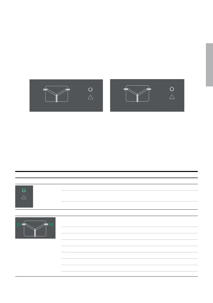
Fig. 3.7 On left: LEDs in OXB_, delayed transition, I - O - II. On right: LEDs in OXA _, open transition I - II.
I - O - II
I - II
Manual
retransfer
Auto
config
Priority
In-phase
monitor
AUTO
!
S1 S2
LOAD
l
ll
O
Lamp
test
l
ON
Off
load
test
ll
ON
Auto
Alarm reset
On
load
test
Bypass
time
delay
Generator
stop delay
4 min
30 s
ΔU 20% / Δf 10%
0
1
2
3
4
5
10
15
20
30
S1 Failure
delay
[s]
S1 Return
delay
[min]
O Position
delay
4 s
0 s
O
OFF
Manual
retransfer
Auto
config
Priority
In-phase
monitor
AUTO
!
S1 S2
LOAD
l
ll
LED Indication Description
Power led
Lamp
test
l
Off
load
test
ll
Auto
Alarm reset
On
load
test
Bypass
time
delay
Generator
stop delay
4 min
30 s
ΔU 10% / Δf 5%
ΔU 15% / Δf 10%
ΔU 20% / Δf 10%
0
1
2
3
4
5
10
15
20
30
S1 Failure
delay
[s]
S1 Return
delay
[min]
Manual
retransfer
On
Priority
No priority
In-phase
monitor
On
AUTO
!
ON, fixed light nnnn Power supply and communication present
nn yy nyy
Power supply present, communication
absent between switch and the HMI
OFF nnnn
No power available for HMI.
S1 and S2 leds
Off
load
test
ll
ON
Auto
Alarm reset
On
load
test
Bypass
time
delay
4 min
30 s
4
5
10
15
20
30
S1 Return
delay
[min]
4 s
0 s
O
OFF
Manual
retransfer
Auto
config
Priority
In-phase
monitor
AUTO
!
LOAD
l
ll
O
S1 S2
ON, fixed light nnnn
defined limits
nn yy nyy Undervoltage
nn y
ynn Unbalance
yyyyyyyyyyyy Overvoltage
nn nn
nnnn nnnn Phase missing
nn Generator stop delay ongoing
OFF nnnn No voltage
LED functionality is common to every HMI-type.