TTF300 FIELD-MOUNT TEMPERATURE TRANSMITTER | OI/TTF300-EN REV. I 29
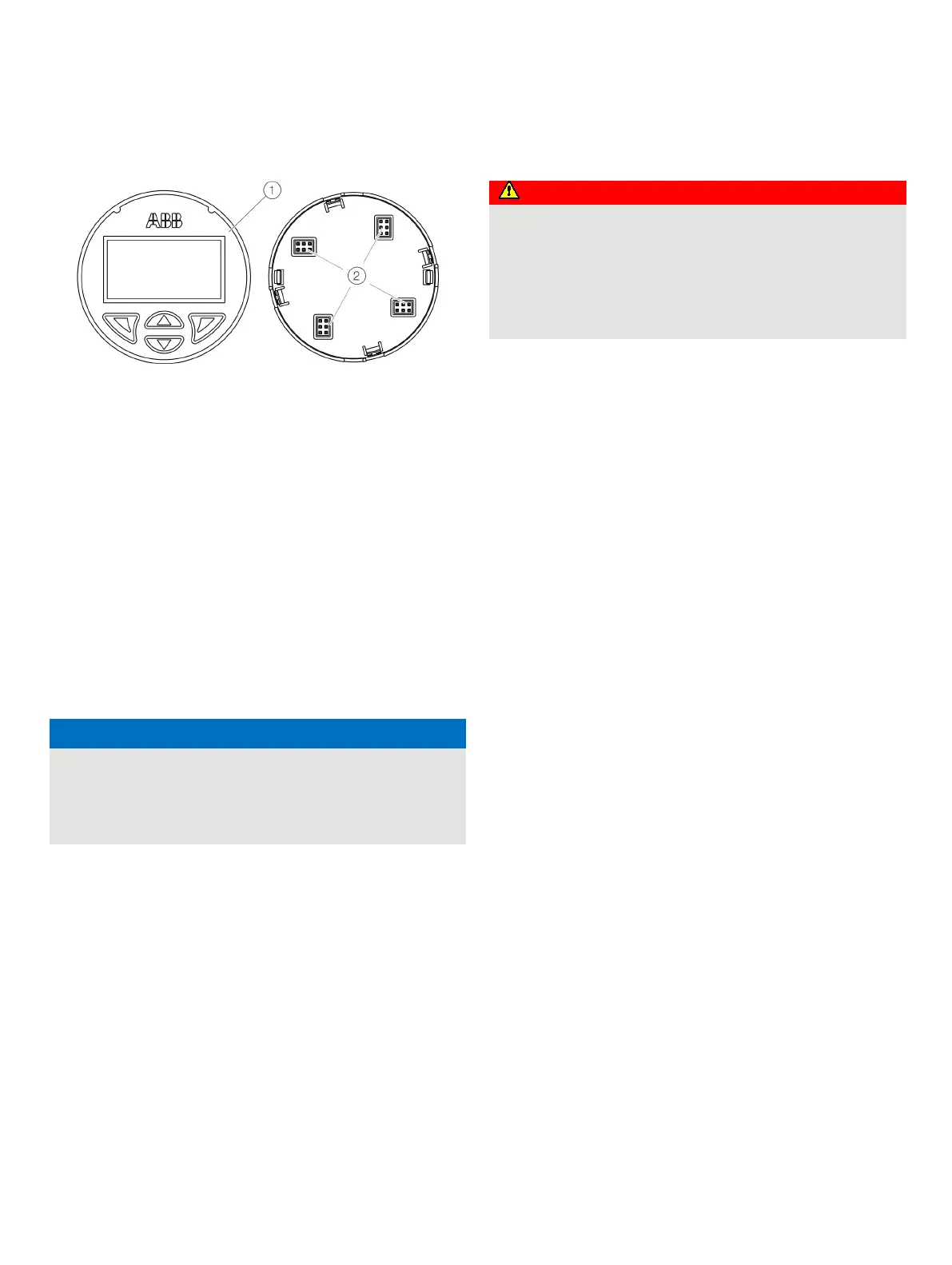
Rotating the LCD indicator
Front view
Rear view of LCD indicator / plug
positions
Figure 19: Rotating the LCD indicator
The position of the LCD indicator can be adjusted to suit the
mounting position of the transmitter, to ensure that the display
is as clearly legible as possible. There are 4 positions at
increments of 90°-.
To adjust the position, proceed as follows:
1. Tighten the lock screw under the housing cover.
2. Release the housing cover by turning it counterclockwise.
3. Carefully pull the LCD indicator to release it from its
bracket.
4. Carefully insert the LCD indicator in the required position.
5. Screw the housing cover back on.
6. Loosen the lock screw until the housing cover is firmly in
place.
Potential adverse effect on the IP rating
• Check the O-ring gasket for damage and replace it if
necessary before closing the housing cover.
• Check that the O-ring gasket is properly seated when
closing the housing cover.
8 Electrical connections
Safety instructions
Improper installation and commissioning of the device
carries a risk of explosion.
For use in potentially explosive atmospheres, observe the
information in Use in potentially explosive atmospheres in
accordance with ATEX and IECEx on page 6 and Use in
potentially explosive atmospheres in accordance with
cFMus, FM and CSA on page 18!
Observe the following instructions:
• The electrical connection may only be established by
authorized specialist personnel and in accordance with
the connection diagrams.
• The relevant regulations must be observed during electric
installation.
• The electrical connection information in the instruction
must be observed; otherwise, the electric IP rating may
be adversely affected.
• Safe isolation of electric circuits which are dangerous if
touched is ensured only if the connected devices satisfy
the requirements of DIN EN 61140 (VDE 0140 Part 1)
(basic requirements for safe isolation).
• To ensure safe isolation, install connection leads separate
from electric circuits which are dangerous if touched, or
implement additional insulation measures.
• Connections must only be established in a dead-voltage
state!
• The transmitter has no switch-off elements. Therefore,
overcurrent protective devices, lightning protection, or
voltage disconnection options must be provided with the
installation.
• The power supply and signal are routed in the same
conductor and should be implemented as a SELV or PELV
circuit in accordance with the relevant standard
(standard version). For the explosion-proof design, the
guidelines in accordance with the Ex standard must be
adhered to.
• You need to check that the available power supply
corresponds to the information on the name plate.
Note
The signal cable wires must be provided with wire end sleeves.
The slotted screws of the connection terminals are tightened
with a size 1 screwdriver (3.5 or 4 mm).